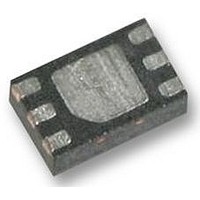
LTC2942CDCB-1#PBF Linear Technology, LTC2942CDCB-1#PBF Datasheet - Page 14

LTC2942CDCB-1#PBF
Manufacturer Part Number
LTC2942CDCB-1#PBF
Description
IC, BATTERY FUEL GAUGE LI-ION 5.5V DFN-6
Manufacturer
Linear Technology
Datasheet
1.LTC2942CDCBTRPBF.pdf
(18 pages)
Specifications of LTC2942CDCB-1#PBF
Battery Management Function
Fuel Gauge, Charge Controller
Battery Type
Li-Ion
Supply Voltage Range
2.7V To 5.5V
Battery Ic Case Style
DFN
No. Of Pins
6
Rohs Compliant
Yes
Lead Free Status / RoHS Status
Lead free / RoHS Compliant
Available stocks
Company
Part Number
Manufacturer
Quantity
Price
Part Number:
LTC2942CDCB-1#PBFLTC2942CDCB-1#TRMPBF
Manufacturer:
LINEAR/凌特
Quantity:
20 000
LTC2942
applicaTions inFormaTion
Read Protocol
The master begins a read operation with a START condition
followed by the seven bit slave address 1100100 and the
R/W bit set to zero, as shown in Figure 6. The LTC2942
acknowledges and then the master sends a command
byte which indicates which internal register the master is
to read. The LTC2942 acknowledges and then latches the
command byte into its internal register address pointer. The
master then sends a repeated START condition followed
by the same seven bit address with the R/W bit now set
to one. The LTC2942 acknowledges and sends the con-
S
ADDRESS
1100100
W
0
A
0
S
S
REGISTER
Figure 10. Reading the LTC2942 Accumulated Charge Registers (C, D)
01h
ADDRESS
1100100
ADDRESS
S
1100100
Figure 8. LTC2942 Serial Bus SDA Alert Response Protocol
ADDRESS
1100100
A
0
Figure 7. Reading the LTC2942 Voltage Register (I, J)
S
Figure 6. Reading the LTC2942 Status Register (A)
DATA
BC
W
ALERT RESPONSE ADDRESS
0
W
0
P
Figure 9. Voltage Conversion Sequence
A
0
W
0
A
0
REGISTER
REGISTER
0001100
A
0
10ms
02h
08h
REGISTER
00h
A
0
A
0
S
ADDRESS
S
1100100
A
0
S
R
ADDRESS
1
1100100
S
ADDRESS
1100100
tents of the requested register. The transmission is ended
when the master sends a STOP condition. If the master
acknowledges the transmitted data byte, the LTC2942
increments its address pointer and sends the contents of
the following register as depicted in Figure 7.
Alert Response Protocol
In a system where several slaves share a common inter-
rupt line, the master can use the alert response address
(ARA) to determine which device initiated the interrupt
(Figure 8).
A
0
ADDRESS
1100100
W
0
DEVICE ADDRESS
A
0
REGISTER
R
1
11001001
R
1
08h
A
0
R
1
A
0
DATA
80h
DATA
A
0
F1h
A
0
S
DATA
01h
ADDRESS
A
1
A
0
1100100
A
0
2942 F08
DATA
P
DATA
01h
A
1
24h
2942 F06
P
R
1
A
1
A
1
A
0
2942 F10
2942 F07
DATA
F1h
P
P
A
0
DATA
80h
A
1
2942 F09
P
2942fa


