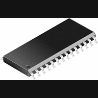
CS8415A-CS Cirrus Logic Inc, CS8415A-CS Datasheet - Page 34

CS8415A-CS
Manufacturer Part Number
CS8415A-CS
Description
IC, DIGITAL AUDIO RECEIVER, SOIC-28
Manufacturer
Cirrus Logic Inc
Specifications of CS8415A-CS
Audio Control Type
Digital
Control Interface
I2C, Serial
Control / Process Application
AV & DVD Receivers, CD-R, Digital Mixing Consoles
Supply Voltage Range
2.85V To 5.5V
Lead Free Status / RoHS Status
Contains lead / RoHS non-compliant
Available stocks
Company
Part Number
Manufacturer
Quantity
Price
Part Number:
CS8415A-CS
Manufacturer:
CIRRUS
Quantity:
20 000
Company:
Part Number:
CS8415A-CSR
Manufacturer:
CirrusLogic
Quantity:
569
Company:
Part Number:
CS8415A-CSZ
Manufacturer:
CIRRUS
Quantity:
108
Part Number:
CS8415A-CSZ
Manufacturer:
CRYSTAL
Quantity:
20 000
34
RCBL
PRO
CHS
NVERR
OSCLK
OLRCK
SDOUT
AUDIO
DGND3
DGND2
DGND
H/S
U
C
ORIG
12
13
14
15
16
17
18
19
20
21
22
24
25
26
28
Receiver Channel Status Block
block. RCBL goes high two frames after the reception of a Z preamble, remains high for 16 frames
while COPY, ORIG, AUDIO, EMPH and PRO are updated, and returns low for the remainder of the
block. RCBL changes on rising edges of RMCK.
PRO Channel Status Bit (Output)
bit in the incoming AES3 data stream. Low indicates Consumer and high indicates Professional.
Channel Select (Input) - Selects which sub-frame’s channel status data is output on the EMPH,
COPY, ORIG, PRO and AUDIO pins. Channel A is selected when CHS is low, channel B is selected
when CHS is high.
No Validity Receiver Error Indicator (Output)
the AES3 receiver. The status of this pin is updated once per frame of incoming AES3 data. Conditions
that cause NVERR to go high are: parity error, and bi-phase coding error, and loss of lock by the PLL.
Serial Audio Output Bit Clock (Input/Output) - Serial bit clock for audio data on the SDOUT pin.
Serial Audio Output Left/Right Clock (Input/Output) - Word rate clock for the audio data on the
SDOUT pin. Frequency will be the output sample rate (Fs).
Serial Audio Output Data (Output) - Audio data serial output pin
Audio Channel Status Bit (Output)
the incoming AES3 data stream. When this bit is low a valid audio stream is indicated.
Digital Ground (Input) - Ground for the digital circuitry in the chip. DGND and AGND should be con-
nected to a common ground area under the chip.
Hardware/Software Mode Control (Input) - Determines the method of controlling the operation of the
CS8415A, and the method of accessing CS and U data. In software mode, device control and CS and U
data access is primarily through the control port, using a microcontroller. Hardware mode provides an
alternate mode of operation and access to the CS and U data through dedicated pins. This pin should be
permanently tied to VL+ or DGND.
User Data (Output) - Outputs user data from the AES3 receiver, clocked by the rising and falling edges
of OLRCK.
Channel Status Data (Output) - Outputs channel status data from the AES3 receiver, clocked by the ris-
ing and falling edges of OLRCK.
Original Channel Status (Output)
egory code and the L bit in the Channel Status bits. A low output indicates that the source of the audio
data stream is a copy not an original. A high indicates that the audio data stream is original. This is also
a start-up option pin, and requires a pull-up or pull-down resistor.
(
-
Output
-
SCMS generation indicator. This is decoded from the incoming cat-
-
Reflects the state of the Professional/Consumer Channel Status
Reflects the state of the audio/non audio Channel Status bit in
) -
Indicates the beginning of a received channel status
-
A high output indicates a problem with the operation of
CS8415A
DS470PP3


