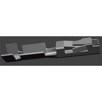
166500-2 Tyco Electronics, 166500-2 Datasheet

166500-2
Specifications of 166500-2
Available stocks
Related parts for 166500-2
166500-2 Summary of contents
Page 1
... Locking Lance 2. REFERENCE MATERIALS 2.1. Revision Summary Updated document to corporate requirements and new logo S E2011 Tyco Electronics Corporation Connectivity Ltd. Company All Rights Reserved TE logo is a trademark. *Trademark. Other product names, logos, or company names might be trademarks of their respective owners. Polarization Feature ...
Page 2
Customer Assistance Reference Part Number 530554 and Product Code G898 are representative numbers that identify the Tandem Spring and Mini--Tandem Spring Housings and Contacts product line. Use of these numbers will identify the product line and expedite your inquiries ...
Page 3
D. Chemical Exposure Do not store contacts near any chemicals listed below as they may cause stress corrosion cracking in the contacts. Alkalies Ammonia Amines Carbonates 3.2. Wire Selection and Preparation The contacts will accept a wire size range of ...
Page 4
Crimped Contact Requirements The contact shall be located in desired tooling and crimped according to the instructions packaged with that tooling. See Section 5, TOOLING, of this document for details on tooling options and instructional materials. Wire insulation shall ...
Page 5
B. Effective Crimp Length For optimum crimp effectiveness, the crimp must be within the area shown and must meet the crimp dimensions provided in Figure 3. Effective crimp length shall be defined as that portion of the wire barrel, excluding ...
Page 6
The side--to--side bend of the contact may not exceed the limits provided. Periodic inspections must be made to ensure crimped contact formation is consistent as shown. NOTE i 0.25 [.010] Max. 0.25 [.010] Max. 3.4. Placement of Crimped Contact ...
Page 7
Connector Keying The Mini--Tandem Spring Housings may be keyed as desired using Keying Plug 531226--1. These plugs insert directly into the empty housing contact cavities, rather than into the loaded receptacles. Refer to Figure 7. The same keying plugs ...
Page 8
HInstall AMP Cable Ties using Hand Tool 734587 Refer to Instruction Sheet 408- - 8816. Optional Cable TieH Stacking Clip Locked Into Connector Housing 4. QUALIFICATIONS Mini--Tandem Spring Housings are Recognized by the Component Program of ...
Page 9
Crimping Die Assemblies S Crimping Die Assemblies for crimping the contacts are available for the full wire size range. They are designed for easy installation and removal in hand crimping tool frame assemblies or applicators. Extraction Tools S Extraction Tools ...
Page 10
WIRE WIRE PRODUCT PRODUCT INSUL INSUL SIZE LINE DIA. (AWG) 0.5--1.02 32-- [.020--.040] [ 020- - 040] TANDEM SPRING 1.4 [.055] 1.4 [.055] 24 24--20 Max. DRefer to the beginning of Section 5, TOOLING for descriptions ...
Page 11
WIRE WIRE PRODUCT PRODUCT INSUL INSUL SIZE LINE DIA. (AWG) TANDEM 1.4 [.055] 24--20 SPRING SPRING Max. Max. (408--9407) (408--8547) 189721--1 (408--2498) (408- - 2498) (409--5862) MINI--TANDEM 0.64--1.37 32--28 SPRING SPRING [.025--.054] [.025 .054] 189722--1 (408- - 2498) (408--2498) (409--5862) ...
Page 12
WIRE WIRE PRODUCT PRODUCT INSUL INSUL SIZE LINE DIA. (AWG) 0.64--1.37 32--28 [.025--.054] (408--8547) (408--8547) 189721--1 MINI--TANDEM (408 2498) (408--2498) SPRING SPRING (409--5862) 0.91 1.37 0.91--1.37 26 26--22 [.036--.054] 189722--1 (408--2498) (408 2498) (409--5862) DRefer to the beginning ...
Page 13
WIRE WIRE PRODUCT PRODUCT INSUL INSUL SIZE LINE DIA. (AWG) 1213805 1 1213805--1 (409--10055) 1213805--2 1213805 2 (409--10055) 1490567--1 (409 10039) 1583527 1 (409--10039) 1583527--1 MINI--TANDEM MINI TANDEM 0.91--1.37 26--22 SPRING [.036--.054] DRefer to the beginning ...
Page 14
Tool Holder Assembly 189928 Pneumatic CERTI- - CRIMP Tool Holder 356304 “Micro” Pneumatic Tooling Assembly 1490567 Hand Actuated System (Without Logic) 189721 626 Pneumatic Crimp Tooling C- - Head ...
Page 15
CERTI- - CRIMP II Battery Powered Crimp Tool Kit 1213805 Cable Tie Installation Tool 734587 SDE Hand Tool Pneumatic Adapter 1583527 Extraction/Lance Reset Tools 843477 and 843996 ...
Page 16
Heavy Duty Miniature Quick- - Change Applicator (Side- - Feed Type) (Typ Applicators for Power Units Applicator 2000 (Typ) Figure 9 (cont’d) 114- 25021 Heavy Duty Industrial (HD Quick- - Change Applicator (Side- - Feed ...
Page 17
AMPOMATOR CLS III Lead- - Making Machines 122500 and 356500 AMP LECTRIC Model “G” Terminating Machine 354500 with Optional Stripping Module 1490501 (Stripping ...
Page 18
VISUAL AID Figure 10 shows a typical application of Tandem Spring and Mini--Tandem Spring Contacts and Connectors. This illustration should be used by production personnel to ensure a correctly applied product. Applications which DO NOT appear correct should be ...


