MS3111E8-4P Amphenol Industrial Operations, MS3111E8-4P Datasheet - Page 58
MS3111E8-4P
Manufacturer Part Number
MS3111E8-4P
Description
MS/PT PROPRIETARY/MIL-C-26482, SERIES I SOLDER TYPE SEALED CONNECTORS SERIES MS3111E ENVIRONMENTAL RESISTING CABLE CONNECTING RECEPTACLES, STRAIGHT BODY STYLE, 8 SHELL SIZE, 8-4 INSERT ARRANGEMENT, 4 CONTACTS
Manufacturer
Amphenol Industrial Operations
Series
Military, MIL-C-26482 Series Ir
Datasheet
1.PT06SE-14-19S-SR.pdf
(80 pages)
Specifications of MS3111E8-4P
Rohs Compliant
NO
Mounting Type
Free Hanging (In-Line)
Connector Type
Receptacle, Male Pins
Number Of Positions
4
Termination
Solder Cup
Orientation
N (Normal)
Fastening Type
Bayonet Lock
Shell Material, Finish
Aluminum, Olive Drab Cadmium Plated
Shell Size - Insert
8-4
Ingress Protection
Environment Resistant
Gender
Receptacle
Contact Gender
Pin
Connector Mounting
Cable
Connector Shell Size
8
Insert Arrangement
8-4
No. Of Contacts
4
Contact Termination
Solder
Contact Material
Copper
Lead Free Status / RoHS Status
Lead free by exemption / RoHS compliant by exemption
Features
-
Shell Size, Military
-
Lead Free Status / RoHS Status
Lead free by exemption / RoHS compliant by exemption


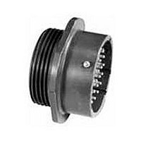
PC07
jam nut receptacle
To complete part number see how to order on page 61.
All dimensions for reference only
Shell
Size
Shell
Size
10
12
14
16
18
20
22
6
8
10
12
14
16
18
20
22
6
8
A
“E” Open Wire Seal
R
PC07E-XX-XXX
P
M
±.010
.286
.331
.375
.442
.486
.530
.573
.641
.685
F
Receptacle Front View
Max.
.692
.692
.692
.692
.692
.692
.692
.754
.754
L
L
Class “E”
Z
1.062
1.188
1.312
1.438
1.562
1.688
±.016
.625
.750
.875
Hex
H
N
1.105
1.230
1.355
1.511
1.636
Max.
.605
.730
.855
.980
N
1.062
1.250
1.375
1.500
1.625
1.812
1.938
±.010
.812
.938
S
Thread
S
H
6-32
6-32
6-32
6-32
6-32
8-32
8-32
8-32
C
1.0000 DS
1.1250 DS
1.2500 DS
1.3750 DS
–
.3750 DS
.5000 DS
.6250 DS
.7500 DS
.8750 DS
Class 2A
F
Thread
A
A
TERMINATION ASSEMBLIES
“A” (SR), “E” (SR) Strain Relief
R
.125
.188
.312
.375
.500
.625
.625
.750
Dia.
G
F
–
Class “A” (SR), “E” (SR)
P
S
PC07A-XX-XXX (SR)
M
PC07E-XX-XXX (SR)
+.016
–.010
.125
.125
.125
.125
.125
.125
.125
.156
.156
K
1.000
1.125
1.188
1.438
1.438
1.625
Max.
.812
.875
56
H
–
Z
L
±.010
.671
.671
.671
.671
.671
.671
.671
.797
.797
M
1.096
1.096
1.096
1.096
1.228
1.228
1.291
1.291
Max.
Receptacle Side View
L
–
G D H
Class “A”, “C”
Panel Thickness
.062
.062
.062
.062
.062
.062
.062
.062
.062
Min.
A
Min.
R
.240
.302
.428
.552
.651
.740
.740
.928
P
P
–
P
M
Max.
.125
.125
.125
.125
.125
.125
.125
.250
.250
1.024
1.149
Min.
.192
.317
.434
.548
.673
.798
.899
“A” General Duty/
“C” Pressurized Receptacle
PC07A-XX-XXX
PC07C-XX-XXX
D
K
1.0000-20 UNEF
1.1250-18 NEF
1.2500-18 NEF
1.3750-18 NEF
1.5000-18 NEF
Z
.4375-28 UNEF
.5625-24 NEF
.6875-24 NEF
.8750-20 UNEF
A
R
Class 2A
“P” Potting Boot
Thread
PC07P-XX-XXX
P
Class “P”
M
R
Max.
.665
.665
.665
.665
.665
.665
.665
.790
.790
L
L
Z
D
Max.
1.110
1.234
1.360
1.484
Max.
.232
.232
.232
.232
.232
.232
.232
.262
.262
.484
.608
.734
.858
.984
N
Z
N
Related parts for MS3111E8-4P
Image
Part Number
Description
Manufacturer
Datasheet
Request
R

Part Number:
Description:
CIRCULAR CONN, RCPT, SIZE 20, 41POS, BOX
Manufacturer:
ITT Cannon
Datasheet:

Part Number:
Description:
RED LED LAMPS
Manufacturer:
MICRO-ELECTRONICS [Micro Electronics]
Datasheet:

Part Number:
Description:
AMPHENOL
Manufacturer:
Amphenol Industrial Operations
Datasheet:

Part Number:
Description:
JAM NUT CONN, RCPT, SIZE 9, 6POS, PANEL
Manufacturer:
Amphenol Industrial Operations
Datasheet:
Part Number:
Description:
PT 41C 41#20 PIN RECP
Manufacturer:
Amphenol Industrial Operations
Part Number:
Description:
PT 41C 41#20 SKT RECP
Manufacturer:
Amphenol Industrial Operations