MS3116F18-32P Amphenol Industrial Operations, MS3116F18-32P Datasheet - Page 32
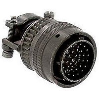
MS3116F18-32P
Manufacturer Part Number
MS3116F18-32P
Description
CIRCULAR CONN PLUG SIZE 18, 32POS, CABLE
Manufacturer
Amphenol Industrial Operations
Type
Cable Plugr
Specifications of MS3116F18-32P
Connector Body Material
Aluminum
Gender
Plug
Contact Gender
Pin
Connector Mounting
Cable
Connector Shell Size
18
Insert Arrangement
18-32
Connector Type
Circular Military
Agency Approvals
UL Recognized
Angle
Straight
Application
True MIL
Brand/series
MS Series
Class
F
Contact Configuration
32#20
Contact Plating
Gold
Contact Size
20
Contact Type
Pin
Current, Rating
7.5 A
Finish, Housing
Olive Drab Cadmium
Housing Type
Metal
Material, Dielectric
Neoprene
Material, Housing
Aluminum
Mating Type
Bayonet
Mounting Type
Free Hanging
Number Of Contacts
32
Primary Type
26482 MIL Spec
Shell Size
18
Special Features
5 Key/Keyway Polarization
Strain Relief
External
Termination
Solder
Voltage, Rating
600 VAC
Wire, Awg
20
Lead Free Status / RoHS Status
Contains lead / RoHS non-compliant
Available stocks
Company
Part Number
Manufacturer
Quantity
Price
Company:

Part Number:
MS3116F18-32P
Manufacturer:
MITSUBISHI
Quantity:
56


PT00 SE (MS3120)
SP00 SE
wall mounting receptacle
* Back panel mounting
All dimensions for reference only.
To complete part number see how to order on page 39.
■
Shell
Shell
Size
10
12
14
16
18
20
22
24
Size
10
12
14
16
18
20
22
24
(MMC) located within .005 of (TP)
8
8
1.062
1.156
1.250
1.375
.594
.719
.812
.906
.969
PT
A
M
1.328
1.328
1.328
1.328
1.328
1.328
1.359
1.359
1.422
Max.
PT00SE-XX-XXX
SP00SE-XX-XXX
MS3120E-XX-XXX
Class “SE”, MS / “E”
“SE” Open Wire Seal
L
(TP)
R
L
1.031
1.125
1.203
1.297
1.375
1.500
.812
.938
SP
–
K
Receptacle Front View
1.080
1.204
1.330
1.454
1.580
N Dia.
Max
N
.560
.704
.825
.954
1.047
1.141
1.234
1.328
1.453
1.578
1.703
PT
.828
.954
Max.
S
1.141
1.266
1.360
1.453
1.532
1.688
1.766
1.891
SP
–
Dia.
.125
.188
.312
.375
.500
.625
.625
.750
.800
G
Class “SE” (SR), MS / “F”
.120
.120
.120
.120
.120
.120
.120
.120
.147
“SE” (SR), MS / “F” Strain Relief
TERMINATION ASSEMBLIES
PT
M
A
± .005
T Dia.
PT00SE-XX-XXX (SR)
SP00SE-XX-XXX (SR)
MS3120F-XX-XXX
2.422
2.422
2.422
2.422
2.537
2.537
2.824
2.824
2.900
Max.
.150
.150
.150
.150
.150
.150
.150
.150
L
SP
–
(TP)
30
S
R
K
L
A Dia.
+.001
1.000
1.125
1.250
1.375
1.500
–.005
.473
.590
.750
.875
(TP)
R
1.094
1.156
1.406
1.406
1.594
1.688
Max.
.781
.844
.969
S
G
N
T Dia.
4 Holes
±.016
N
.062
.062
.062
.062
.062
.062
.094
.094
.094
K
Receptacle Side View
1.034
1.159
1.284
D Dia.
Max.
.444
.558
.683
.808
.909
.431
.431
.431
.431
.431
.431
.556
.556
.589
–
PT
+.010
–.000
M
Class “SP”, MS / “P”
PT00SP-XX-XXX
SP00SP-XX-XXX
“SP” Potting Boot
A
M
.462
.462
.462
.462
.462
.556
.556
.589
SP
–
1.656
1.656
1.656
1.656
1.656
1.750
1.750
1.782
Max.
L
–
L
Max. Panel Thickness
K
.094
.094
.094
.094
.094
.094
.219
.219
.219
PT
D
P*
N
1.110
1.234
1.360
1.484
1.610
N Dia.
Max.
.734
.858
.984
–
.125
.125
.125
.125
.125
.219
.219
.219
SP
–
Related parts for MS3116F18-32P
Image
Part Number
Description
Manufacturer
Datasheet
Request
R

Part Number:
Description:
CONN PLUG 4POS W/PINS SOLDER
Manufacturer:
Amphenol Industrial Operations

Part Number:
Description:
CONN PLUG 6POS W/PINS SOLDER
Manufacturer:
Amphenol Industrial Operations

Part Number:
Description:
CONN PLUG 3POS W/SOCKET SOLDER
Manufacturer:
Amphenol Industrial Operations

Part Number:
Description:
CONN PLUG 4POS W/SOCKET SOLDER
Manufacturer:
Amphenol Industrial Operations

Part Number:
Description:
CONN PLUG 2POS W/SOCKET SOLDER
Manufacturer:
Amphenol Industrial Operations

Part Number:
Description:
JAM NUT CONN, RCPT, SIZE 9, 6POS, PANEL
Manufacturer:
Amphenol Industrial Operations
Datasheet:

Part Number:
Description:
PT 41C 41#20 PIN RECP
Manufacturer:
Amphenol Industrial Operations
Part Number:
Description:
PT 41C 41#20 SKT RECP
Manufacturer:
Amphenol Industrial Operations