MS27501B13C SUNBANK, MS27501B13C Datasheet - Page 14
MS27501B13C
Manufacturer Part Number
MS27501B13C
Description
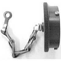
PLUG PROTECTIVE CAP, ALUMINUM ALLOY
Manufacturer
SUNBANK
Datasheet
1.MS27501B13C.pdf
(37 pages)
Specifications of MS27501B13C
Connector Shell Size
13
Connector Body Material
Aluminum Alloy
Peak Reflow Compatible (260 C)
No
Accessory Type
Dust Cap
For Use With
MIL-C-38999 Series I Circular Connector Plugs
Lead Free Status / RoHS Status
Contains lead / RoHS non-compliant


Straight Plug
MS27473
(MS service class E, P, T)
Straight Plug Grounded
MS27484
(MS service class E, P, T)
MIL-DTL-38999 Series II Connectors
Performance Specifications-Pages 3-4
Contacts, Sealing Plugs, Assembly Tools - Pages 22, 27-28
Contact Arrangements - Pages 20-21
Shell
Shell
Size
Size
10
12
14
16
18
20
22
24
10
12
14
16
18
20
22
24
8
8
1.014 (25.76)
1.140 (28.96)
1.264 (32.11)
1.389 (35.28)
1.514 (38.46)
1.014 (25.76)
1.140 (28.96)
1.264 (32.11)
1.389 (35.28)
1.514 (38.46)
.485 (12.32)
.606 (15.39)
.765 (19.43)
.890 (22.61)
.485 (12.32)
.606 (15.39)
.765 (19.43)
.890 (22.61)
Dia. Max.
Dia. Max.
A
A
1.030 (26.16)
1.155 (29.34)
1.280 (32.51)
1.405 (35.69)
1.530 (38.86)
1.640 (40.66)
1.765 (44.83)
1.030 (26.16)
1.155 (29.34)
1.280 (32.51)
1.405 (35.69)
1.530 (38.86)
1.640 (40.66)
1.765 (44.83)
.749 (19.02)
.858 (21.79)
.749 (19.02)
.858 (21.79)
Dia. Max.
Dia. Max.
G
G
KJG6
KJ6
NOTE: For backshell dimensions and configurations, see pages 26 and 27.
NOTE: For backshell dimensions and configurations, see pages 26 and 27.
1.050 (26.67)
1.172 (29.77)
1.304 (33.12)
1.435 (36.45)
1.560 (39.62)
1.688 (42.88)
1.050 (26.67)
1.172 (29.77)
1.304 (33.12)
1.435 (36.45)
1.560 (39.62)
1.688 (42.88)
.630 (16.00)
.752 (19.10)
.925 (23.50)
.630 (16.00)
.752 (19.10)
.925 (23.50)
Dia. Max.
Dia. Max.
P
P
G DIA.
G DIA.
1-1/16-18UNEF-2A
1-3/16-18UNEF-2A
1-5/16-18UNEF-2A
1-7/16-18UNEF-2A
1-1/16-18UNEF-2A
1-3/16-18UNEF-2A
1-5/16-18UNEF-2A
1-7/16-18UNEF-2A
11/16-24UNEF-2A
13/16-20UNEF-2A
15/16-20UNEF-2A
11/16-24UNEF-2A
13/16-20UNEF-2A
15/16-20UNEF-2A
7/16-28UNEF-2A
9/16-24UNEF-2A
7/16-28UNEF-2A
9/16-24UNEF-2A
14
Thread
Thread
T
T
POLARIZING
KEYWAY
POLARIZING
KEYWAY
BLUE BAND
(INDICATES REAR
RELEASE CONTACT
RETENTION SYSTEM)
1.026 (26.06)
1.026 (26.06)
1.026 (26.06)
1.026 (26.06)
1.026 (26.06)
1.026 (26.06)
1.026 (26.06)
1.026 (26.06)
1.104 (28.04)
DIA.
1.026 (26.06)
1.026 (26.06)
1.026 (26.06)
1.026 (26.06)
1.026 (26.06)
1.026 (26.06)
1.026 (26.06)
1.026 (26.06)
1.104 (28.04)
Straight
P
Straight
E
DIA.
BLUE BAND
(INDICATES REAR
RELEASE CONTACT
RETENTION SYSTEM)
E
Specifications and dimensions subject to change
DIA.
P
A
Overall Length With Backshells
Overall Length With Backshells
DIA.
A
Cable Clamp
1.555 (39.50)
1.555 (39.50)
1.555 (39.50)
1.790 (45.47)
1.790 (45.47)
1.790 (45.47)
1.790 (45.47)
1.930 (49.02)
1.930 (49.02)
Cable Clamp
1.555 (39.50)
1.555 (39.50)
1.555 (39.50)
1.790 (45.47)
1.790 (45.47)
1.790 (45.47)
1.790 (45.47)
1.930 (49.02)
1.930 (49.02)
Cannon KJ
F
F
Dimensions shown in mm
www.ittcannon.com
T THREAD
T THREAD
Potting Max.
1.020 (25.91)
1.020 (25.91)
1.020 (25.91)
1.020 (25.91)
1.020 (25.91)
1.020 (25.91)
1.020 (25.91)
1.020 (25.91)
1.080 (27.43)
Potting Max.
1.020 (25.91)
1.020 (25.91)
1.020 (25.91)
1.020 (25.91)
1.020 (25.91)
1.020 (25.91)
1.020 (25.91)
1.020 (25.91)
1.080 (27.43)
P
P