58448-3 Tyco Electronics, 58448-3 Datasheet - Page 3
58448-3
Manufacturer Part Number
58448-3
Description
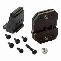
Pro Crimper II SDE Die Set
Manufacturer
Tyco Electronics
Series
Pro-Crimper III, AMPLIMITE®r
Type
Pro Crimpersr
Specifications of 58448-3
Wire Size (awg)
28-20
Connector Type
Crimp Terminals
Crimp Handle
A9996-ND
Crimp Or Cable Size
20-28 AWG
Product
Crimping, Stripping & Cutting Tools & Drills
For Use With
Pro Crimper II Crimp Tool & D-Sub 20DF Pin & Socket Contacts AMPLIMITE
Lead Free Status / RoHS Status
na
Lead Free Status / RoHS Status
na, Not applicable / Not applicable
Other names
A9814


Rev E
Contact
Retainer
CAUTION
CAUTION
1. Hold the tool so that the front (locator side) is
facing you. Squeeze tool handles together and
allow them to open fully.
2. Insert the contact—mating end first—into the
hole in the locator which corresponds with the
appropriate crimping chamber. Make sure that the
open “U” of the wire barrel and insulation barrel
face the stationary jaw.
3. Slide the locator contact retainer out from
between the dies (spring tension will pull the
locator down). Make sure that the wire stop enters
the contact wire stop slot between the wire barrel
and contact shoulder. Release contact retainer.
4. Hold the contact in position, and squeeze the
tool handles together until ratchet engages
sufficiently to hold the contact in position. Do NOT
deform insulation barrel or wire barrel.
5. Insert stripped wire into contact insulation and
wire barrels until it is butted against the wire stop,
as shown in Figure 3.
6. Holding the wire in place, squeeze tool handles
together until ratchet releases. Allow tool handles
to open and remove crimped contact.
Tool Wire
Size Markings
!
!
Locator
Do NOT attempt to close the tool handles when
locator contact retainer is between the dies.
Damage to the tool jaws or locator may result.
Make sure that both sides of the contact
insulation barrel are started evenly into the
crimping chamber. Do NOT attempt to crimp an
improperly positioned contact.
Back of Tool
(Wire Side)
Figure 3
Wire
5. CRIMP HEIGHT INSPECTION
Crimp height inspection is performed through the use
of a micrometer with a modified anvil, commonly
referred to as a crimp--height comparator. TE does
not manufacture or market crimp--height comparators.
Detailed information on obtaining and using
crimp--height comparators can be found in instruction
sheet 408--7424.
Proceed as follows:
NOTE
7. Check the contact crimp height as described in
Section 5, CRIMP HEIGHT INSPECTION. If
necessary, adjust the crimp height as described in
Section 6, CRIMP HEIGHT ADJUSTMENT.
1. Refer to Figure 4 and select the maximum size
wire for the crimping chamber.
2. Refer to Section 3, CRIMPING PROCEDURE,
and crimp the contact accordingly.
3. Using a crimp height comparator, measure the
wire barrel crimp height as shown in Figure 4. If the
crimp height conforms to that shown, the tool is
considered dimensionally correct. If not, the tool
must be adjusted. Refer to Section 6, CRIMP
HEIGHT ADJUSTMENT.
i
Locator in
Contact Wire
Stop Slot
The crimped contact may stick in the crimping
area, but can be removed by pushing downward
on the top of the locator (see Figure 3).
Wire Strip Length
Wire Inserted to
Locator Wire Stop
Tool Stationary
Jaw
408- 9357
3 of 5