224928-1 Tyco Electronics, 224928-1 Datasheet - Page 4
224928-1
Manufacturer Part Number
224928-1
Description
PROCRIMP HT&D MOD PLUG ESR
Manufacturer
Tyco Electronics
Series
Pro-Crimper™ IIIr
Type
Crimp Tool Assemblyr
Specifications of 224928-1
Rohs Compliant
NA
Tool Type
Hand Crimper
Features
Side Entry, Ratchet
Product
Crimping, Stripping & Cutting Tools & Drills
Description/function
Hand crimp tool assembly
Lead Free Status / RoHS Status
Not applicable / Not applicable
For Use With/related Products
Modular Strain Relief
For Use With
558527-3 - STRAIN RELIEF EXT MOD PLUGA9130 - CONN STRAIN RELIEF MODULAR TIN
Lead Free Status / Rohs Status
Lead free / RoHS Compliant
Other names
A9800


5. CRIMP NEST
The crimp nest may be removed and rotated 180 to
accommodate two sizes of insulation. Dimensions for
these wire insulation sizes are shown in Figure 5.
6. CRIMP HEIGHT ADJUSTMENT
4
[.332 +.006]
[.332 +.006]
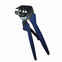
PRO-CRIMPER III Hand Tool Assembly 224928-1 with Die Assembly 224928-2
8.43 +0.15
8.43 +0.15
of 4
1. Remove the lockscrew from the ratchet
adjustment wheel.
2. With a screwdriver, adjust the ratchet wheel
from the back of the tool.
3. Observe the ratchet adjustment wheel. If a
tighter crimp is required, rotate the adjustment
wheel COUNTERCLOCKWISE to a
higher–numbered setting. If a looser crimp is
required, rotate the adjustment wheel
CLOCKWISE to a lower–numbered setting.
4. Replace the lockscrew.
5. Make a sample crimp and visually check the
crimp height (refer to Figure 4). If the crimp is
acceptable, replace and secure the lockscrew. If
the crimp is unacceptable, continue to adjust the
ratchet, and again measure a sample crimp.
For 4.70-5.08 mm [.185-.200 in.] Insulation Dia.
For 5.08-5.46 mm [.200-.215 in.] Insulation Dia.
[.240 +.004]
[.210 +.004]
6.10 +0.10
5.33 +0.10
Figure 5
(Figure 6)
.185-.200
.200-.215
Tyco Electronics Corporation
7. MAINTENANCE
Ensure that the tool and dies are clean by wiping
them with a clean, soft cloth. Remove any debris with
a clean, soft brush. Do not use objects that could
damage the tool. When not in use, keep handles
closed to prevent objects from becoming lodged in
the crimping dies, and store in a clean, dry area.
8. VISUAL INSPECTION
The crimping dies should be inspected on a regular
basis to ensure that they have not become worn or
damaged. Inspect the crimping chambers for
flattened, chipped, worn, or broken areas. If damage
or abnormal wear is evident, the tool must be
replaced. See Section 9, REPLACEMENT.
9. REPLACEMENT
Customer–replaceable parts are shown in Figure 1. If
the dies are damaged or worn excessively, they must
be replaced. Order replaceable parts through your
Tyco Electronics Representative, or call
1–800–526–5142, or send a facsimile of your
purchase order to 1–717–986–7605, or write to:
10. REVISION SUMMARY
CUSTOMER SERVICE (38–35)
TYCO ELECTRONICS CORPORATION
P.O. BOX 3608
HARRISBURG, PA 17105–3608
S Updated document to corporate requirements
S Added new Section 5, and renumbered
S Added new Figure 5 and renumbered
Ratchet
Adjustment
Wheel
Screwdriver
Lockscrew
(Typ)
Figure 6
408-4167
Rev
A