EM14R0D-R20-L032N Bourns Inc., EM14R0D-R20-L032N Datasheet - Page 4
EM14R0D-R20-L032N
Manufacturer Part Number
EM14R0D-R20-L032N
Description
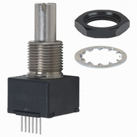
ENCODER OPT ROTARY 32PPR WO/SW
Manufacturer
Bourns Inc.
Series
EM14r
Type
Optical Encoderr
Datasheet
1.EM14C0D-E24-L032S.pdf
(5 pages)
Specifications of EM14R0D-R20-L032N
Pulses Per Revolution
32
Encoder Type
Optical
Output Type
Quadrature (Incremental)
Voltage - Supply
5VDC
Actuator Type
6mm Dia Slotted End
Detent
No
Built In Switch
No
Mounting Type
Panel, PCB Through Hole
Orientation
Vertical
Termination Style
PC Pin
Rotational Life (cycles Min)
1M
No. Of Channels
2
Rotational Speed Max
120rpm
Supply Voltage Range
4.75VDC To 5.25VDC
Rotational Life Cycles
1000000
Torque Max
1.5in-oz
Encoder Output
Quadrature
Detents
No
Motion
Rotary
Number Of Channels
2
Mounting Style
Through Hole
Index Output
Not Indexed
Encoder Signal
Digital Square Wave
Shaft Style
Slot
Shaft Diameter (mm)
6mm
Operating Supply Voltage (typ)
5VDC
Operating Temperature Min Deg. C
-40C
Operating Temperature Max Deg. C
70C
Terminal Type
PC Pins
Mechanical Life
2000000
Output
2 bit Quadrature Code
Shaft Type
Slotted
With Switch
With
Operating Temperature Range
- 40 C to + 70 C
Product
Optical
Sensor Supply Voltage
4.75VDC To 5.25VDC
Rohs Compliant
Yes
Encoder Resolution
32CPR
Leaded Process Compatible
Yes
Lead Free Status / RoHS Status
Lead free / RoHS Compliant
Lead Free Status / RoHS Status
Lead free / RoHS Compliant, Lead free / RoHS Compliant


Cable Assembly, Connector on One End
Cable Assembly, Connector on Both Ends
(.098 ± .015)
Radial (shown with optional mounting bracket)
(.103 ± .015)
Axial (shown with optional mounting bracket)
2.49 ± .38
2.62 ± .38
Cable/Connector Options
Terminal Confi gurations
STRIPPED AND TINNED
(.590 ± .005)
14.99 ± .13
(.590 ± .010)
3312 - 2 mm SMD Trimming Potentiometer
EM14 - 14 mm Rotary Optical Encoder w/Switch
100 % MATTE TIN
14.99 ± .25
(.100)
2.54
(.676)
17.17
(.676)
17.17
REF.
6x28 AWG x
(.581 ± .010)
15.76 ± .25
6x28 AWG x
RIBBON CABLE
RIBBON CABLE
THICKNESS
(.063)
(.050)
1.60
PCB
1.27
REF.
(.050)
A
1.27
PITCH
A
PITCH
X
(.059)
(.015)
0.381
1.5
(.416)
10.57
PIN 1 - RED STRIPE
WIDE
THICK
PIN 1 - RED STRIPE
REF.
(.157)
3.98
REF.
PCB THICKNESS
(.597 ± .010)
(.315)
15.16 ± .25
(.310)
8.0
(.048)
7.87
REF.
1.22
(.063)
REF.
1.60
2 x CONNECTOR
(.246)
CONNECTOR
FOR
FOR
(.049)
x
x
REF.
6.25
1.24
(.050)
(.050)
1.27
1.27
(.018)
(.018)
.457
.457
PITCH
PITCH
CHANNEL “A”
CHANNEL “A”
MOMENTARY
MOMENTARY
DIA. PINS
DIA. PINS
Customers should verify actual device performance in their specifi c applications.
GROUND
GROUND
SWITCH
SWITCH
(.236)
(.236)
6.0
6.0
RECEPTACLE
RECEPTACLE
(.106)
REF.
2.7
x
x
(.039)
(.039)
1.0
1.0
HARDWARE
NUMBER
H-190-4
H-190-2
H-190-1
H-190-3
CHANNEL “B”
CHANNEL “B”
Specifi cations are subject to change without notice.
POWER
POWER
6 PLCS.
DIMENSIONS:
DESCRIPTION
CABLE ASSEMBLY,
CONNECTOR
ON ONE END
CABLE ASSEMBLY,
CONNECTOR
ON ONE END
CABLE ASSEMBLY,
CONNECTOR
ON BOTH ENDS
CABLE ASSEMBLY,
CONNECTOR
ON BOTH ENDS
Recommended PCB Layout
Recommended PCB Layout
6 PLCS.
(.025)
(.025)
DIA.
DIA.
.64
.64
(INCHES)
(.575)
14.61
MM
(.050 ± .005)
(.050 ± .005)
(12.0 ± .197)
(12.0 ± .197)
1.27 ± .13
“A” DIM.
152.4 ± 5.0
(6.0 ± .197)
304.8 ± 5.0
152.4 ± 5.0
(6.0 ± .197)
304.8 ± 5.0
1.27 ± .13
5 PLCS.
5 PLCS.
(.246 ± .003)
(.310 ± .003)
(.068 ± .004)
(.068 ± .004)
6.25 ± .08
7.87 ± .08
1.73 ± .10
1.73 ± .10
2 PLCS.
2 PLCS.
DIA.
DIA.
Related parts for EM14R0D-R20-L032N
Image
Part Number
Description
Manufacturer
Datasheet
Request
R

Part Number:
Description:
ENCODER OPT ROTARY 16PPR W/SW
Manufacturer:
Bourns Inc.
Datasheet:

Part Number:
Description:
ENCODER OPT ROTARY 16PPR WO/SW
Manufacturer:
Bourns Inc.
Datasheet:
Part Number:
Description:
ENCODER OPT ROTARY 64PPR WO/SW
Manufacturer:
Bourns Inc.
Datasheet:
Part Number:
Description:
ENCODER OPT ROTARY 64PPR WO/SW
Manufacturer:
Bourns Inc.
Datasheet:
Part Number:
Description:
ENCODER OPT ROTARY 32PPR W/SW
Manufacturer:
Bourns Inc.
Datasheet:
Part Number:
Description:
ENCODER OPT ROTARY 64PPR W/SW
Manufacturer:
Bourns Inc.
Datasheet:
Part Number:
Description:
Optical Encoder
Manufacturer:
Bourns Inc.
Datasheet:
Part Number:
Description:
Optical Encoder
Manufacturer:
Bourns Inc.
Datasheet:
Part Number:
Description:
Optical Encoder
Manufacturer:
Bourns Inc.
Datasheet:
Part Number:
Description:
Optical Encoder
Manufacturer:
Bourns Inc.
Datasheet:

Part Number:
Description:
Manufacturer:
Bourns, Inc.
Datasheet:
Part Number:
Description:
11mm Potentiometer
Manufacturer:
Bourns, Inc.
Datasheet: