EM14C0D-E28-L016N Bourns Inc., EM14C0D-E28-L016N Datasheet - Page 2
EM14C0D-E28-L016N
Manufacturer Part Number
EM14C0D-E28-L016N
Description
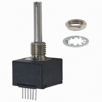
ENCODER OPT ROTARY 16PPR WO/SW
Manufacturer
Bourns Inc.
Series
EM14r
Datasheet
1.EM14C0D-E24-L032S.pdf
(5 pages)
Specifications of EM14C0D-E28-L016N
Pulses Per Revolution
16
Encoder Type
Optical
Output Type
Quadrature (Incremental)
Voltage - Supply
5VDC
Actuator Type
1/8" Dia Slotted End
Detent
No
Built In Switch
No
Mounting Type
Panel, PCB Through Hole
Orientation
Vertical
Termination Style
PC Pin
Rotational Life (cycles Min)
1M
No. Of Channels
2
Rotational Speed Max
120rpm
Supply Voltage Range
4.75VDC To 5.25VDC
Rotational Life Cycles
1000000
Torque Max
1.5in-oz
Encoder Output
Quadrature
Output
2 bit Quadrature Code
Shaft Type
Slotted
With Switch
With
Operating Temperature Range
- 40 C to + 70 C
Product
Optical
Sensor Supply Voltage
4.75VDC To 5.25VDC
Rohs Compliant
Yes
Encoder Resolution
16CPR
Leaded Process Compatible
Yes
Lead Free Status / RoHS Status
Lead free / RoHS Compliant
Lead Free Status / RoHS Status
Lead free / RoHS Compliant, Lead free / RoHS Compliant


Additiional Features
■
■
■
■
Cable and Connector Options:
H-190-4 = 6 ” Cable with Female Connector (0.050 ”/1.27 mm pitch centers in-line) and stripped/tinned leads
H-190-1 = 6 ” Cable with Female Connector (0.050 ”/1.27 mm pitch centers in-line) on both ends
H-190-2 = 12 ” Cable with Female Connector (0.050 ”/1.27 mm pitch centers in-line) and stripped/tinned leads
H-190-3 = 12 ” Cable with Female Connector (0.050 ”/1.27 mm pitch centers in-line) on both ends
For other cable and connector options, please contact the factory.
Part Numbering System
Splashproof shaft seal
Recommended for human/machine interface applications (HMI)
Cable/connector option
Optional bracket
EM14 14 mm Rotary Optical Encoder
Code
E M 1 4 A 0 D - C 2 4
A
C
R
EM14 - 14 mm Rotary Optical Encoder w/Switch
MODEL NO. DESIGNATOR
Description
3/8 " D x 3/8 " L Threaded
1/4 " D x 1/4 " L Threaded
10 mm D x 9.5 mm L Threaded
BUSHING DESIGNATOR
SHAFT STYLE (See Outline Drawing for Details)
Code
ANTI-ROTATION LUG/BRACKET OPTION
Code
Code
M
B
C
R
0
1
E
B
D
A
Description
No Detent
32 Detents (Available for
8 or 32 PPR only)
Description
1/4 " Dia. Slotted End
1/4 " Dia. Flatted End
1/8 " Dia. Slotted End
6 mm Dia. Slotted End
6 mm Dia. Flatted End
Description
A/R Lug
Bracket (No hardware/no cable or
connector)
None
DETENT OPTION
Code
24
28
20
25
SHAFT LENGTH DESIGNATOR
Length (FMS)
3/4 "
7/8 "
20 mm
25 mm
Available w/Bushing
Available w/
Bushing
A
A
C
R
R
A, C
A, C
R, U
R, U
- L 0 3
Customers should verify actual device performance in their specifi c applications.
Code
TERMINAL CONFIGURATION
R
L
Code
Description
Axial Multi-Purpose Pin
Radial Multi-Purpose Pin
0
1
2
3
4
CABLE/CONNECTOR OPTION
RESOLUTION (Pulses Per Revolution)
2
Code
08
16
32
64
Description
No Cable/Connector
6 ” Cable with Female Connector
(0.050 ”/1.27 mm pitch centers in-line)
and stripped/tinned leads
6 ” Cable with Female Connector
(0.050 ”/1.27 mm pitch centers in-line)
on both ends
12 ” Cable with Female Connector
(0.050 ”/1.27 mm pitch centers in-line)
and stripped/tinned leads
12 ” Cable with Female Connector
(0.050 ”/1.27 mm pitch centers in-line)
on both ends
Code
S
H
N
S
Description
8 PPR
16 PPR
32 PPR
64 PPR
Specifi cations are subject to change without notice.
Description
Push Switch (Standard)
Push Switch (High Force)
No Switch
SWITCH OPTION
Related parts for EM14C0D-E28-L016N
Image
Part Number
Description
Manufacturer
Datasheet
Request
R

Part Number:
Description:
ENCODER OPT ROTARY 64PPR WO/SW
Manufacturer:
Bourns Inc.
Datasheet:

Part Number:
Description:
ENCODER OPT ROTARY 64PPR W/SW
Manufacturer:
Bourns Inc.
Datasheet:
Part Number:
Description:
ENCODER OPT ROTARY 64PPR W/SW
Manufacturer:
Bourns Inc.
Datasheet:

Part Number:
Description:
ENCODER OPT ROTARY 16PPR W/SW
Manufacturer:
Bourns Inc.
Datasheet:
Part Number:
Description:
ENCODER OPT ROTARY 32PPR W/SW
Manufacturer:
Bourns Inc.
Datasheet:

Part Number:
Description:
Optical Encoder
Manufacturer:
Bourns Inc.
Datasheet:
Part Number:
Description:
ROTARY OPTICAL ENCODER - 14MM
Manufacturer:
Bourns Inc.
Datasheet:

Part Number:
Description:
ROTARY OPTICAL ENCODER - 14MM
Manufacturer:
Bourns Inc.
Datasheet:

Part Number:
Description:
Manufacturer:
Bourns, Inc.
Datasheet:
Part Number:
Description:
11mm Potentiometer
Manufacturer:
Bourns, Inc.
Datasheet:
Part Number:
Description:
Manufacturer:
Bourns, Inc.
Datasheet: