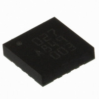
BMA145 Bosch Sensortec, BMA145 Datasheet - Page 8

BMA145
Manufacturer Part Number
BMA145
Description
3-AXIS ACCELEROMETER ANALOG I/F
Manufacturer
Bosch Sensortec
Specifications of BMA145
Axis
X, Y, Z
Acceleration Range
±4g
Sensitivity
300mV/g
Voltage - Supply
1.8 V ~ 3.5 V
Output Type
Analog
Bandwidth
1.5kHz
Interface
Parallel
Mounting Type
Surface Mount
Package / Case
16-LGA
For Use With
828-1011 - BMA145 DAUGHTERCARD FOR DEV KIT
Lead Free Status / RoHS Status
Lead free / RoHS Compliant
Other names
828-1002-2
3
3.1
The BMA145 is a fully calibrated, triaxial low-g analog acceleration sensor. It allows
measurements of static as well as dynamic accelerations in all three dimensions. Due to its
three perpendicular axes it gives the absolute orientation in a gravity field and enables free-fall
detection. The sensor is set up as a two-chip arrangement consisting of a three-channel
capacity differential MEMS acceleration-sensing element and an application specific integrated
circuit (ASIC). Both parts are embedded in a standard, surface mountable land grid array
package (LGA). In the following, the LGA packed two-chip arrangement is defined as sensor
module.
The accelerometer features a low-pass characteristic, with a bandwidth limited to 1.5 kHz
(nominal value). This value can further be reduced using external capacitors to improve or
customize noise level. It is advised to reduce bandwidth to minimum value required in the
application.
The bandwidth of all output pins can be selected by the value of the capacitors connected to the
Ax, Ay and Az output. Each channel behaves like an independent low-pass RC filter, given by
the internal 33kΩ resistor and the external capacitor. The resulting RC low pass filter on Ax, Ay
an Az is also valid for the multiplexer output pin. Do not connect an additional external capacitor
on the multiplexer output pin. Refer to chapter 4.8 for details.
3.1.1
The production of the sensing element is based on standard semiconductor- and standard
MEMS processes. The main steps are layer deposition, layer masking and layer structuring in a
technology cycle, similar to the standard semiconductor manufacturing. In detail, the process
cycle starts with the deposition of a thick epitaxial layer on a sacrificial oxide. The large
thickness allows the design of working capacitances of up to 1pF. The poly layer is patterned by
deep reactive ion etching in an inductively coupled plasma (DRIE-ICP, the so-called Bosch
process). A large aspect ratio and a very high anisotropy is achieved by periodic passivation of
the side walls in between the etch intervals. Afterwards the sacrificial layer is removed. The
sensing element is hermetically sealed by a bulk micromachined cap to prevent damages of the
structure by dicing, packaging and operation of the device.
3.1.2
The ASIC is produced in a standard CMOS process. It evaluates, corrects and amplifies the
output signal of the MEMS acceleration-sensing element. Simplified considered, the ASIC
consists mainly out of 3 capacity voltage converters and 3 signal conditioners, a channel
multiplexer, a digital to analog converter an EEPROM memory and an internal RC oscillator. For
customized testing an electrostatic force to the sensor electrodes can be induced and compared
with a nominal condition. Thus, a general statement about the functional capability of the sensor
module can be made at any time.
Rev. 1.1
© Bosch Sensortec GmbH reserves all rights even in the event of industrial property rights. We reserve all rights of disposal such
as copying and passing on to third parties. BOSCH and the symbol are registered trademarks of Robert Bosch GmbH, Germany.
Note: Specifications within this document are subject to change without notice.
BMA145 features
General description
MEMS element
ASIC
Triaxial, analog acceleration sensor
Data sheet
BMA145
Page 8
Bosch Sensortec
02 April 2008


