MCP1640RD-4ABC Microchip Technology, MCP1640RD-4ABC Datasheet - Page 15
MCP1640RD-4ABC
Manufacturer Part Number
MCP1640RD-4ABC
Description
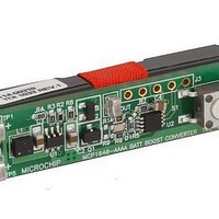
BOARD REF DES AAAA BAT BOOST
Manufacturer
Microchip Technology
Type
Battery Managementr
Specifications of MCP1640RD-4ABC
Main Purpose
DC/DC, Step Up
Outputs And Type
1, Non-Isolated
Voltage - Output
3.3V
Current - Output
130mA
Voltage - Input
1.5V
Regulator Topology
Boost
Frequency - Switching
500kHz
Board Type
Fully Populated
Utilized Ic / Part
MCP1640
Product
Power Management Development Tools
Silicon Manufacturer
Microchip
Silicon Core Number
MCP1640, PIC12F
Kit Application Type
Power Management
Application Sub Type
Boost Converter
Core Architecture
PIC
For Use With/related Products
MCP1640, PIC12F617
Lead Free Status / RoHS Status
Lead free / RoHS Compliant
Power - Output
-
Lead Free Status / Rohs Status
Lead free / RoHS Compliant
Available stocks
Company
Part Number
Manufacturer
Quantity
Price
Company:

Part Number:
MCP1640RD-4ABC
Manufacturer:
MICROCHIP
Quantity:
12 000


Installation and Operation
Periodically, the microcontroller will come out from Sleep mode for a short period of
time to search if its power supply (V
), which comes from MCP1640 V
pin,
DD
OUT
reaches 2.3V threshold. This is accomplished by the internal analog comparator of the
microcontroller.
This compares a fraction of V
(from R4) with the 0.6V internal voltage reference.
OUT
To avoid losing power on the passive components and reduce the complexity of the
schematic, the application also uses MCP1640’s feedback network (R2-R3-R4) as the
input to the PIC comparator.
The PIC12F617 microcontroller works down to 2.0V V
. If a 2.3V threshold is
DD
detected, the GP2 pin of the microcontroller will set the EN pin of the MCP1640 high
for a short time, to pump up the output capacitor to a 3.3V regulated voltage. After
that, EN is pulled down again and MCP1640 enters into the True Output Disconnect
Shutdown option. V
is sustained by the output capacitor (C2) for approximately 2
OUT
seconds until it reaches the 2.3V threshold.
Generally, the EN drive signal frequency depends on the MCP1640’s output capacitor
value and PIC12F617’s sleep current. The typical time to charge the output capacitor
to 3.3V is 750 ns, with a load less than 10 µA.
The EN signal is inverted using the transistor Q1 to ensure the start of the application
when a battery is inserted.
By pressing the button S1, the GP1 microcontroller port switches the P-MOS
transistor ON (Q2), powering the load. The load is supplied for a fixed period of time
(approximately 25 seconds), unless the button is pressed.
The PIC12F617 measures the battery voltage when the switch load (Q2) is ON. If the
battery voltage is lower than 0.8V, the LED (D1) will flash. Battery voltage is measured
using the R7-C4 filter and the A/D channel present on pin 3 (GP4) of the
microcontroller.
2.2.3
Programming the PIC12F617 Microcontroller
For board evaluation, Microchip provides a firmware package, downloadable from
Microchip’s web site. The board is factory programmed for an active 10 seconds output,
after the button S1 is pressed. The green LED on the board flashes when a low battery
condition (less than 0.8V input) is detected, but the board will operate at the lowest
input voltage possible. All parameters may be changed in firmware to the desired value,
according to the output/input capability. The source code is rich in comments and helps
the user to define the board.
HI-TECH C compiler is used to compile the source code and create the hex files for
downloading to the reference board. The HI-TECH compiler is available for download
on Microchip’s web site. The compiler is not included with the evaluation board kit.
Header J3 can be used for in-system circuit programming. J3 is not populated on the
board. A five pin header connector may be soldered in J3’s place. A PICkit™3
programmer may be connected to J3 to program the evaluation board.
© 2010 Microchip Technology Inc.
DS51922A-page 15
Related parts for MCP1640RD-4ABC
Image
Part Number
Description
Manufacturer
Datasheet
Request
R

Part Number:
Description:
Manufacturer:
Microchip Technology Inc.
Datasheet:
Part Number:
Description:
Manufacturer:
Microchip Technology Inc.
Datasheet:
Part Number:
Description:
Manufacturer:
Microchip Technology Inc.
Datasheet:
Part Number:
Description:
Manufacturer:
Microchip Technology Inc.
Datasheet:
Part Number:
Description:
Manufacturer:
Microchip Technology Inc.
Datasheet:
Part Number:
Description:
Manufacturer:
Microchip Technology Inc.
Datasheet:
Part Number:
Description:
Manufacturer:
Microchip Technology Inc.
Datasheet:
Part Number:
Description:
Manufacturer:
Microchip Technology Inc.
Datasheet: