LM22671EVAL/NOPB National Semiconductor, LM22671EVAL/NOPB Datasheet - Page 2
LM22671EVAL/NOPB
Manufacturer Part Number
LM22671EVAL/NOPB
Description
BOARD EVALUATION FOR LM22671
Manufacturer
National Semiconductor
Series
SIMPLE SWITCHER®r
Datasheets
1.LM22671MRE-ADJNOPB.pdf
(18 pages)
2.LM22671EVALNOPB.pdf
(6 pages)
3.LM22671EVALNOPB.pdf
(18 pages)
Specifications of LM22671EVAL/NOPB
Main Purpose
DC/DC, Step Down
Outputs And Type
1, Non-Isolated
Voltage - Output
3.3V
Current - Output
500mA
Voltage - Input
4.5 ~ 42 V
Regulator Topology
Buck
Frequency - Switching
500kHz
Board Type
Fully Populated
Utilized Ic / Part
LM22671
Lead Free Status / RoHS Status
Lead free / RoHS Compliant
Power - Output
-
Lead Free Status / Rohs Status
Compliant
Other names
*LM22671EVAL
*LM22671EVAL/NOPB
LM22671EVAL
LM22671EVAL
*LM22671EVAL/NOPB
LM22671EVAL
LM22671EVAL


www.national.com
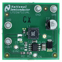
Evaluation Board Setup
Before applying power to the LM22671 evaluation board, all
external connections should be verified. The external power
supply must be turned off and connected with proper polarity
to the VIN and GND posts. A load resistor or electronic load
should be connected between the VOUT and GND posts as
desired. Both the VIN and VOUT connections should use the
closest GND posts respective to VIN or VOUT. The output
voltage can be monitored with a multi-meter or oscilloscope
at the VOUT post.
Once all connections to the evaluation board have been ver-
ified, input power can be applied. A load resistor or electronic
load does not require connection during startup. If the EN test
point is left floating, the output voltage will ramp up when an
input voltage is applied. Make sure that the external power
supply (input voltage power source) is capable of providing
enough current so that the adjusted output voltage can be
obtained. Keep in mind that the startup current will be greater
than the steady state current.
Synchronization and Adjustable
Frequency
A SYNC test point is provided to allow synchronization of the
LM22671 to an external clock signal. Space for a frequency
adjust resistor, R3, is also provided. Refer to the LM22671
datasheet for more details about the synchronizing and ad-
justable frequency features.
Precision Enable
The EN test point provided on the LM22671 evaluation board
can be used to shut down the LM22671 when connecting this
test point to ground.
Soft-Start
The capacitor C6 sets the amount of soft-start. A 1 µF soft-
start capacitor is used for slow start-up. See the LM22671
datasheet for details about the soft-start function.
Ref #
C1
C2
C3
C4
C5
C6
D1
R1
R2
R3
U1
L1
TABLE 1. LM22671EVAL Bill of Materials for VOUT = 3.3V, Designed for 500 mA Output Current
39 µH 1.11A WE-PD M
22 µF 63V electrolytic
2.2 uF 50V ceramic
22 µF 6.3V ceramic
60V 1A CMSH1-60
10 nF 50V ceramic
1 µF 10V ceramic
Not populated
Not populated
1.54 kΩ 1%
976Ω 1%
Value
National Semiconductor
Central Semiconductor
2
Component Selection
Before changing the default components refer to the
LM22671 datasheet for information regarding component se-
lection. The WEBENCH
tool is also available at www.national.com.
The output voltage is adjustable with resistors R1 and R2
shown in the schematic. Any changes to these evaluation
board feedback resistors may require changes to the inductor
and output capacitor values. It is especially important to
change the output capacitor, C4, if the output voltages are
adjusted higher than 5V. The Schottky diode, D1, has a volt-
age rating of 60V to allow for a 42V maximum input voltage.
If the input voltage is below 38V, a 40V Schottky diode may
be used with a lower forward voltage to improve efficiency.
The input capacitor, C2, is not always required. This capacitor
is placed on the evaluation board to make the application ro-
bust and minimize input voltage ringing if power is suddenly
applied. Capacitor C2 also helps stabilize the transfer function
of the converter loop. The input capacitor C1 provides the
main contribution to the switch current. Both capacitors are
selected with appropriate values intended only for the evalu-
ation of the LM22671. For production designs, the impedance
of the power source as well as the ripple current rating of the
selected input capacitors need to be taken into consideration
and modified accordingly. See the LM22671 datasheet for
more information.
Output capacitor C5 is not populated but space is provided to
add a second output capacitor. This second output capacitor
may be used to further reduce output voltage ripple.
Panasonic
Supplier
Coilcraft
Wurth
TDK
TDK
TDK
TDK
-
-
-
-
®
designer online circuit simulation
CRCW0603976RFKEA
CRCW06031K54FKEA
C3225X7R1H225K
C1608X7R1H103K
MSS7341-393MLD
C2012X5R0J226M
C1608Y5V1A105Z
LM22671MR-ADJ
EEEFK1J220XP
Part Number
7447779139
CMSH1-60
Related parts for LM22671EVAL/NOPB
Image
Part Number
Description
Manufacturer
Datasheet
Request
R

Part Number:
Description:
National Semiconductor [8-Bit D/A Converter]
Manufacturer:
National Semiconductor
Datasheet:
Part Number:
Description:
National Semiconductor [Media Coprocessor]
Manufacturer:
National Semiconductor
Datasheet:
Part Number:
Description:
Digitally Controlled Tone and Volume Circuit with Stereo Audio Power Amplifier, Microphone Preamp Stage and National 3D Sound
Manufacturer:
National Semiconductor
Datasheet:
Part Number:
Description:
Digitally Controlled Tone and Volume Circuit with Stereo Audio Power Amplifier, Microphone Preamp Stage and National 3D Sound
Manufacturer:
National Semiconductor
Datasheet:
Part Number:
Description:
AC97 Rev 2 Codec with Sample Rate Conversion and National 3D Sound
Manufacturer:
National Semiconductor
Part Number:
Description:
Manufacturer:
National Semiconductor
Datasheet:
Part Number:
Description:
Manufacturer:
National Semiconductor
Datasheet:
Part Number:
Description:
General Purpose, Low Voltage, Low Power, Rail-to-Rail Output Operational Amplifiers
Manufacturer:
National Semiconductor
Datasheet:
Part Number:
Description:
8-bit 20 MSPS flash A/D converter.
Manufacturer:
National Semiconductor
Datasheet:
Part Number:
Description:
Low Noise Quad Operational Amplifier
Manufacturer:
National Semiconductor
Datasheet:
Part Number:
Description:
Quad Differential Line Receivers
Manufacturer:
National Semiconductor
Datasheet:
Part Number:
Description:
Quad High Speed Trapezoidal? Bus Transceiver
Manufacturer:
National Semiconductor
Datasheet:
Part Number:
Description:
Dual Line Receiver
Manufacturer:
National Semiconductor
Datasheet:
Part Number:
Description:
TTL to 10k ECL Level Translator with Latch
Manufacturer:
National Semiconductor
Datasheet: