LMK04000BEVAL/NOPB National Semiconductor, LMK04000BEVAL/NOPB Datasheet - Page 15
LMK04000BEVAL/NOPB
Manufacturer Part Number
LMK04000BEVAL/NOPB
Description
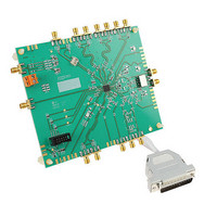
BOARD EVAL PRECISION CLOCK PLL
Manufacturer
National Semiconductor
Series
PowerWise®r
Datasheets
1.LMK04010BISQENOPB.pdf
(54 pages)
2.LMK04002BEVAL.pdf
(56 pages)
3.LMK04002BEVAL.pdf
(38 pages)
Specifications of LMK04000BEVAL/NOPB
Main Purpose
Timing, Clock Conditioner
Embedded
No
Utilized Ic / Part
LMK04000
Primary Attributes
122.88 MHz VCXO
Secondary Attributes
Integrated PLL & VCO
Lead Free Status / RoHS Status
Lead free / RoHS Compliant
Other names
LMK04000BEVAL
LMK04000BEVAL
LMK04000BEVAL


Power Supply
The Power Supply should be a low noise power supply. An Agilent 6623A Triple power supply with LC filters on
the output to reduce noise was used in creating these evaluation board instructions.
Phase Noise / Spectrum Analyzer
For measuring phase noise an Agilent E5052A Signal Source Analyzer is recommended. An Agilent E4445A
PSA Spectrum Analyzer with the Phase Noise option is also usable although the architecture of the E5052A is
superior for phase noise measurements. At frequencies less than 100 MHz the local oscillator noise of the
E4445A is too high and measurements will reflect the E4445A’s internal local oscillator performance, not the
device under test.
Oscilloscope
For measuring delay an Agilent Infiniium DSO81204A was used.
Connector Name
OSCin/OSCin*
Vtune1
Vtune2
LD_TP
uWire
L M K 0 4 0 X X
Input/Output
Input/Output
Input
Output
Output
Output
Recommended Test Equipment
E V A L U A T I O N
module or on-board crystal-based VCXO, an external VCXO may be
attached to the OSCin/OSCin* SMA connectors. Either a differential or
single-ended device may be used. If a single-end device is used,
OSCin* should be tied to GND through a capacitor that matches the
AC-coupling capacitor value used for the OSCin pin. Pads for this
capacitor are located close to the OSCin* pin. This capacitor is not
placed for either of the default configurations of the board. See the
LMK04000 data sheet for OSCin port signal specifications.
Tuning voltage output from the loop filter for PLL1. This control voltage
should be connected to the voltage control pin if an external VCXO is
used.
Note: Resistor R143 must be populated with a zero ohm resistor to
control an off-board VCXO.
R84 must be populated with a zero ohm resistor.
signal lines. Each of these signals can be monitored through test points
on the board.
to a multiplexer inside the device and may be programmed with a
variety of internal signals for monitoring internal device functions and
troubleshooting. See data sheet for further explanation. The lock detect
signal is accessible through this pin.
Description
If the evaluation board is not configured with an on-board VCXO
Available to monitor the tuning voltage for the internal VCO. Resistor
10-pin header programming interface for the board. CLK, DATA and LE
Test point attached to the LD pin of the device. The LD pin is attached
15
B O A R D
O P E R A T I N G
I N S T R U C T I O N S
Related parts for LMK04000BEVAL/NOPB
Image
Part Number
Description
Manufacturer
Datasheet
Request
R

Part Number:
Description:
Low-noise Clock Jitter Cleaner With Cascaded Plls
Manufacturer:
National Semiconductor Corporation
Datasheet:
Part Number:
Description:
Lmk04000 Family Of Precision Clock Conditioners Low-noise Clock Jitter Cleaner With Cascaded Plls
Manufacturer:
National Semiconductor Corporation
Datasheet:

Part Number:
Description:
National Semiconductor [8-Bit D/A Converter]
Manufacturer:
National Semiconductor
Datasheet:
Part Number:
Description:
National Semiconductor [Media Coprocessor]
Manufacturer:
National Semiconductor
Datasheet:
Part Number:
Description:
Digitally Controlled Tone and Volume Circuit with Stereo Audio Power Amplifier, Microphone Preamp Stage and National 3D Sound
Manufacturer:
National Semiconductor
Datasheet:
Part Number:
Description:
Digitally Controlled Tone and Volume Circuit with Stereo Audio Power Amplifier, Microphone Preamp Stage and National 3D Sound
Manufacturer:
National Semiconductor
Datasheet:
Part Number:
Description:
AC97 Rev 2 Codec with Sample Rate Conversion and National 3D Sound
Manufacturer:
National Semiconductor
Part Number:
Description:
Manufacturer:
National Semiconductor
Datasheet:
Part Number:
Description:
Manufacturer:
National Semiconductor
Datasheet:
Part Number:
Description:
General Purpose, Low Voltage, Low Power, Rail-to-Rail Output Operational Amplifiers
Manufacturer:
National Semiconductor
Datasheet:
Part Number:
Description:
8-bit 20 MSPS flash A/D converter.
Manufacturer:
National Semiconductor
Datasheet:
Part Number:
Description:
Low Noise Quad Operational Amplifier
Manufacturer:
National Semiconductor
Datasheet:
Part Number:
Description:
Quad Differential Line Receivers
Manufacturer:
National Semiconductor
Datasheet:
Part Number:
Description:
Quad High Speed Trapezoidal? Bus Transceiver
Manufacturer:
National Semiconductor
Datasheet: