ISL59605IRZ-EVALZ Intersil, ISL59605IRZ-EVALZ Datasheet - Page 2
ISL59605IRZ-EVALZ
Manufacturer Part Number
ISL59605IRZ-EVALZ
Description
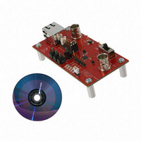
EVALUATION BOARD FOR ISL5960X
Manufacturer
Intersil
Series
MegaQ™r
Specifications of ISL59605IRZ-EVALZ
Main Purpose
Video, Cable Equalizer/Amplifier
Embedded
No
Utilized Ic / Part
ISL59605IRZ
Secondary Attributes
LED Status Indicators
Lead Free Status / RoHS Status
Lead free / RoHS Compliant
Primary Attributes
-


• INVERT: The Invert signal can be an input or an output (see
• FREEZE: The “FREEZE” switch determines the operational
LEDs
There are 5 LEDs at the bottom right of the board that indicate
the current state of the EQ_DIS, COLOR, INVERT, LOCKED, and
FREEZE signals, as well as test pins for that signal directly above.
The LEDs are only enabled when the LED ENABLE jumper is in
place. When the LEDs are illuminated, they will draw additional
supply current from the 5V supply. To accurately measure the
supply current of the ISL5960x without any LED current, remove
the jumper to turn off all the LEDs.
Related Documents
• ISL5960x Datasheet (FN6739)
• ISL59605-SPI-EVALZ Evaluation Board (with Serial Interface)
datasheet for more info). The default position for automatic
inversion detection and correction is the middle position (“F” for
floating - not 0 or 1).
mode. The recommended mode is “Lock Until Reset”, which is
the middle (“LOCKEDtoFREEZE”) position. Slide the switch left
to the “0” position to put the part in Automatic Update mode.
The “1” position freezes the equalizer in its current state. See
the datasheet for more detailed information on the locking
modes.
Operation (AN1588)
2
Application Note 1598
Troubleshooting
1. Make sure all the switches are in the correct default position
2. Verify that there is 5V across the power supply pins, and that
3. Probe the IN+ and IN- pins for a video signal. For Cat x inputs,
4. If you see the correct input signal on IN+ and IN- but are still
5. Probe the OUT test pin with a scope to see if there is a video
as described previously.
the board is drawing ~70mA of current. If you are seeing less
current, the EQ_DIS switch may be set to the wrong position.
you should see a signal on both inputs (with IN- being the
inverse of the signal on IN+). For coax inputs, you should see
a signal on IN+ and a DC voltage on IN-. If you do not see the
expected signals, inspect your cables, video sources, etc. For
Cat x signals, verify that the jumpers in the jumper block are
set correctly. If you are not certain which pair of Cat x wires is
carrying the signal, you can probe the middle row of 8 pins in
the jumper block, where you should see the signal on 2 of
them.
not seeing a valid output signal, toggle the INVERT switch high
and low and then back to the center position to reset the chip.
signal. If you see a composite video signal, inspect your
cables, video receiver, etc.
January 21, 2011
AN1598.1
Related parts for ISL59605IRZ-EVALZ
Image
Part Number
Description
Manufacturer
Datasheet
Request
R

Part Number:
Description:
Intersil Corporation [CMOS Serial Controller Interface]
Manufacturer:
Intersil Corporation
Datasheet:
Part Number:
Description:
Manufacturer:
Intersil Corporation
Datasheet:
Part Number:
Description:
357-036-542-201 CARDEDGE 36POS DL .156 BLK LOPRO
Manufacturer:
Intersil Corporation
Datasheet:
Part Number:
Description:
1024-Word x 4-Bit LSI Static RAM
Manufacturer:
Intersil Corporation
Datasheet:
Part Number:
Description:
General Purpose NPN Transistor Arrays FN341.4
Manufacturer:
Intersil Corporation
Datasheet:
Part Number:
Description:
CMOS 16-Bit Microprocessor
Manufacturer:
Intersil Corporation
Datasheet:
Part Number:
Description:
Manufacturer:
Intersil Corporation
Datasheet:
Part Number:
Description:
Manufacturer:
Intersil Corporation
Datasheet:
Part Number:
Description:
Manufacturer:
Intersil Corporation
Datasheet:
Part Number:
Description:
Manufacturer:
Intersil Corporation
Datasheet:
Part Number:
Description:
CMOS 6-Bit Latch and Decoder Memory Interfaces
Manufacturer:
Intersil Corporation
Datasheet:
Part Number:
Description:
CA3046General Purpose NPN Transistor Arrays
Manufacturer:
Intersil Corporation
Datasheet:
Part Number:
Description:
Manufacturer:
Intersil Corporation
Datasheet:
Part Number:
Description:
TR909 DLC/FLC SLIC with Low Power Standby
Manufacturer:
Intersil Corporation
Datasheet:
Part Number:
Description:
Manufacturer:
Intersil Corporation
Datasheet: