CBC-EVAL-10 Cymbet Corporation, CBC-EVAL-10 Datasheet - Page 12
CBC-EVAL-10
Manufacturer Part Number
CBC-EVAL-10
Description
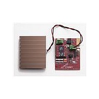
ENERCHIP CC SEH EVAL KIT
Manufacturer
Cymbet Corporation
Series
EnerChip™ CCr
Type
Energy Harvestingr
Datasheet
1.CBC-EVAL-10.pdf
(15 pages)
Specifications of CBC-EVAL-10
Main Purpose
Power Management, Renewable Energy
Embedded
No
Utilized Ic / Part
CBC3150, CBC51100
Primary Attributes
Thin Film Rechargeable Solid State Battery
Secondary Attributes
Solar Energy Harvester
Maximum Operating Temperature
+ 70 C
Product
Power Management Development Tools
For Use With/related Products
EnerChip CBC51100
Lead Free Status / RoHS Status
Lead free / RoHS Compliant
Lead Free Status / RoHS Status
Lead free / RoHS Compliant, Lead free / RoHS Compliant
Other names
859-1012
Available stocks
Company
Part Number
Manufacturer
Quantity
Price
Company:

Part Number:
CBC-EVAL-10
Manufacturer:
Cymbet Corporation
Quantity:
135


Using Other Energy Harvesting Transducers
CBC-EVAL-10 includes a standard amorphous silicon solar panel (Sanyo AM1815 type) configured as 8 series-
connected cells on a glass substrate. The output voltage and current vary with incident light intensity, wave-
length, and load impedance.
DC sources other than the PV cell provided with the CBC-EVAL-10 may also be used as the energy harvesting
power transducer. While the CBC-EVAL-10 module has a Zener diode at the transducer input to limit high volt-
age excursions at 5.6V, it is recommended that any DC transducer input be limited to 5.5V under all antici-
pated operating conditions. The minimum input voltage required to activate the internal charge pump of the
CBC3150 is 2.5V. At <2.5V, the EnerChips will not charge and the power management circuit will not function.
It is recommended that the input power source have a maximum power operating point above 3.0V. Operating
characteristics for most transducers are typically available from the manufacturer’s data sheet. An example
photovoltaic cell operating curve is shown below. Output impedance, operating voltage, and peak power point
can also be verified by empirical measurements. To determine the peak power point of a given PV cell, measure
the load voltage and current as a variable load impedance across the transducer is swept over a broad enough
range where the peak power point can be found by finding the maximum product of the measured load voltage
and current.
Once the peak power point of the PV cell has been determined, the CBC3150 operating point can be adjusted
to match the PV cell. This is done by adding a resistor divider R2 and R3 to the CBC-EVAL-10 module. As
shipped, those resistors are not populated. Cut the solder trace in the R2 location prior to adding the resistor.
Resistor values should be sized according the guidelines in the CBC3150 data sheet. It is important to note
that the resistor divider will present a permanent parasitic load to the PV cells and therefore the calculation
should be made to determine whether the standard CBC3150 impedance matching setpoint of ~3V - though it
might not be at the peak power point of a particular PV cell - is preferred to the more optimized setpoint when
considering the additional parasitic load on the PV resulting from the added resistor divider.
DS-72-20 Rev A
©2011 Cymbet Corporation • Tel: +1-763-633-1780 • www.cymbet.com
Current-Voltage Curve
CBC-EVAL-10 EnerChip CC EH Evaluation Kit
V
I
V
I
P
SC
OP
OC
OP
MAX
: Short-circuit current
: Optimum operating current
: Open-circuit voltage
: Optimum operating voltage
: Maximum operating power
Page 12 of 15
Related parts for CBC-EVAL-10
Image
Part Number
Description
Manufacturer
Datasheet
Request
R

Part Number:
Description:
ENERCHIP CC EVAL KIT
Manufacturer:
Cymbet Corporation
Datasheet:

Part Number:
Description:
ENERCHIP EP ENERGY HARVEST EVAL
Manufacturer:
Cymbet Corporation
Datasheet:

Part Number:
Description:
ENERCHIP EH SEH EVAL KIT
Manufacturer:
Cymbet Corporation
Datasheet:

Part Number:
Description:
INDUCTIVE CHARGING EVAL KIT
Manufacturer:
Cymbet Corporation
Datasheet:

Part Number:
Description:
LCD Graphic Display Modules & Accessories GEMboard Display Driver Board
Manufacturer:
Amulet Technologies LLC
Datasheet:

Part Number:
Description:
ENERCHIP CC EVAL KIT
Manufacturer:
Cymbet Corporation
Datasheet:
Part Number:
Description:
ENERCHIP EP ENERGY HARVEST EVAL
Manufacturer:
Cymbet Corporation
Datasheet: