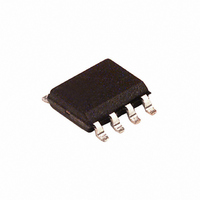
EL5172ISZ-T7A Intersil, EL5172ISZ-T7A Datasheet - Page 12

EL5172ISZ-T7A
Manufacturer Part Number
EL5172ISZ-T7A
Description
IC LINE RCVR 250MHZ SGL 8SOIC
Manufacturer
Intersil
Datasheet
1.EL5172ISZ.pdf
(15 pages)
Specifications of EL5172ISZ-T7A
Amplifier Type
Differential
Number Of Circuits
1
Output Type
Differential
Slew Rate
800 V/µs
Gain Bandwidth Product
100MHz
-3db Bandwidth
250MHz
Current - Input Bias
6µA
Voltage - Input Offset
7000µV
Current - Supply
5.6mA
Current - Output / Channel
60mA
Voltage - Supply, Single/dual (±)
4.75 V ~ 11 V, ±2.38 V ~ 5.5 V
Operating Temperature
-40°C ~ 85°C
Mounting Type
Surface Mount
Package / Case
8-SOIC (0.154", 3.90mm Width)
Lead Free Status / RoHS Status
Lead free / RoHS Compliant
Typical Applications
As the signal is transmitted through a cable, the high
frequency signal will be attenuated. One way to compensate
for this loss is to boost the high frequency gain at the
receiver side.
Level Shifter and Signal Summer
The EL5172 and EL5372 contains two pairs of differential
pair input stages, which make sure that the inputs are all
high impedance inputs. To take advantage of the two high
impedance inputs, the EL5172 and EL5372 can be used as
a signal summer to add two signals together. One signal can
be applied to VIN+, the second signal can be applied to REF
and V
V
Also, the EL5172 and EL5372 can be used as a level shifter
by applying a level control signal to the REF input.
O
=
IN
(
V
Z
- is ground. The output is equal to Equation 6:
O
IN
= 100Ω
+
+
V
REF
)
R
×
3
Gain
50Ω
50Ω
C
1
EL5173,
EL5172,
EL5373
EL5372
OR
12
R
1
V
V
V
V
FB
IN
INB
REF
EL5172,
EL5372
FIGURE 25. TWISTED PAIR CABLE RECEIVER
FIGURE 26. COMPENSATED LINE RECEIVER
R
50
50
2
EL5172, EL5372
(EQ. 6)
Z
O
= 100Ω
V
OUT
50Ω
50Ω
GAIN
(dB)
1 + R
V
V
V
V
FB
IN
INB
REF
2
/(R
f
A
EL5172,
EL5372
1
+ R
0Ω
3
)
f
C
1 + R
2
V
/R
OUT
September 14, 2010
1
f
FN7311.9


