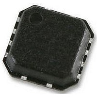
ADV3220ACPZ Analog Devices Inc, ADV3220ACPZ Datasheet - Page 16

ADV3220ACPZ
Manufacturer Part Number
ADV3220ACPZ
Description
IC MULTIPLEXER 2:1 16LFCSP
Manufacturer
Analog Devices Inc
Datasheet
1.ADV3219ACPZ.pdf
(20 pages)
Specifications of ADV3220ACPZ
Supply Voltage Range
± 4.5V To ± 5.5V
Supply Current
7.5mA
Digital Ic Case Style
LFCSP
No. Of Pins
8
Operating Temperature Range
-40°C To +85°C
Svhc
No SVHC (18-Jun-2010)
Base Number
322
Lead Free Status / RoHS Status
Lead free / RoHS Compliant
ADV3219/ADV3220
THEORY OF OPERATION
The ADV3219/ADV3220 are dual-supply, high performance 2:1
analog multiplexers, optimized for switching between multiple
video sources. High peak slew rates enable wide bandwidth oper-
ation for large input signals. Internal compensation provides for
high phase margin, allowing low overshoot and fast settling for
pulsed inputs. Low enabled and disabled power consumption make
the ADV3219 and ADV3220 ideal for constructing larger arrays.
The multiplexer is organized as two input transconductance
stages tied in parallel with a single output transimpedance stage
followed by a unity-gain buffer. Internal voltage feedback sets
the gain. The ADV3219 is configured as a gain of 1, whereas the
ADV3220 uses a resistive feedback network and ground buffer to
realize gain-of-2 operation (see Figure 56). The ground reference
for the ADV3220 is taken from the exposed pad of the package.
To minimize spurious signals on the output, tie the exposed pad
to a low inductance, quiet ground plane.
GND
IN0
IN1
Figure 56. Conceptual Diagram of ADV3220
V+
V–
V+
V–
V+
V–
×1
1kΩ
1kΩ
OUT
Rev. 0 | Page 16 of 20
When not in use, place the OUT pin in a low power, high
impedance disabled mode via the EN logic input. This mode
provides a wideband high impedance on the OUT pin that is
useful when paralleling multiple ADV3219/ADV3220 devices
in a system to create larger switching arrays.
Switching between the inputs is controlled with the SELECT
logic input, with IN0 selected when the SELECT line is a logical
low and IN1 selected when the select line is a logical high. When
EN is a logical low, the output is enabled and connected to one
of the two inputs depending on the state of the SELECT pin.
When EN is a logical high, the output is placed in a high
impedance mode.
When not in use, the output can be placed in a low power, high
impedance disabled mode via the EN logic input.


