MC56F8256VLF Freescale Semiconductor, MC56F8256VLF Datasheet - Page 48
MC56F8256VLF
Manufacturer Part Number
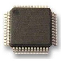
MC56F8256VLF
Description
DSC 64K FLASH 60MHZ 48-LQFP
Manufacturer
Freescale Semiconductor
Series
56F8xxxr
Datasheets
1.TWR-56F8257.pdf
(88 pages)
2.MC56F8245VLD.pdf
(14 pages)
3.MC56F8245VLD.pdf
(2 pages)
4.MC56F8245VLD.pdf
(629 pages)
Specifications of MC56F8256VLF
Core Processor
56800E
Core Size
16-Bit
Speed
60MHz
Connectivity
CAN, I²C, LIN, SCI, SPI
Peripherals
LVD, POR, PWM, WDT
Number Of I /o
39
Program Memory Size
64KB (32K x 16)
Program Memory Type
FLASH
Ram Size
4K x 16
Voltage - Supply (vcc/vdd)
3 V ~ 3.6 V
Data Converters
A/D 10x12b, D/A 1x12b
Oscillator Type
Internal
Operating Temperature
-40°C ~ 105°C
Package / Case
48-LQFP
Product
DSCs
Processor Series
56800E
Core
56800E
Device Million Instructions Per Second
60 MIPs
Maximum Clock Frequency
60 MHz
Number Of Programmable I/os
39
Data Ram Size
8 KB
Operating Supply Voltage
3.3 V
Maximum Operating Temperature
+ 105 C
Mounting Style
SMD/SMT
Minimum Operating Temperature
- 40 C
On-chip Adc
12 bit, 5 Channel
Lead Free Status / RoHS Status
Lead free / RoHS Compliant
Eeprom Size
-
Lead Free Status / Rohs Status
Details
Available stocks
Company
Part Number
Manufacturer
Quantity
Price
Company:

Part Number:
MC56F8256VLF
Manufacturer:
AD
Quantity:
23
Company:
Part Number:
MC56F8256VLF
Manufacturer:
MOTOLOLA
Quantity:
413
Company:
Part Number:
MC56F8256VLF
Manufacturer:
Freescale Semiconductor
Quantity:
10 000
Part Number:
MC56F8256VLF
Manufacturer:
FREESCALE
Quantity:
20 000


Specifications
6.2.4
6.2.4.1
A user can unsecure a secured device by programming the word 0x0000 into program flash location 0x00 7FF7. After
completing the programming, the JTAG TAP controller and the device must be reset to return to normal unsecured operation.
The user is responsible for directing the device to invoke the flash programming subroutine to reprogram the word 0x0000 into
program flash location 0x00 7FF7. You can do so, for example, by toggling a specific pin or downloading a user-defined key
through serial interfaces.
6.2.4.2
The user can temporarily bypass security through a “back door” access scheme, using a four-word key to temporarily unlock
the flash. “Back door” access requires support from the embedded software. This software would typically permit an external
user to enter the four-word code through one of the communications interfaces and then use it to attempt the unlock sequence.
If the input matches the four-word code stored at location 0x00 7FFC–0x00 7FFF in the flash memory, the device immediately
becomes unsecured (at runtime) and internal memory is accessible via the JTAG/EOnCE port. Refer to the device’s reference
manual for details. The key must be entered in four consecutive accesses to the flash, so this routine should be designed to run
in RAM.
6.3
To analyze a product’s failures in the field, the recommended method of unsecuring a secured device appears in
“Presenting Back Door Access Key to the Flash
to access the subroutines in flash memory. An alternative method for performing analysis on a secured device is to mass-erase
and reprogram the flash memory with the original code, but also to modify or not program the security word.
7
7.1
The MC56F825x/MC56F824x is fabricated in high-density, low-power, low-leakage CMOS process with 5 V–tolerant,
TTL-compatible digital inputs. The term 5 V–tolerant refers to the capability of an I/O pin, built on a 3.3 V–compatible process
technology, to withstand a voltage up to 5.5 V without damaging the device. Many systems have a mixture of devices designed
for 3.3 V and 5 V power supplies. In such systems, a bus may carry both 3.3 V–compatible and 5 V–compatible I/O voltage
levels (a standard 3.3 V I/O is designed to receive a maximum voltage of 3.3 V 10% during normal operation without causing
damage). This 5 V–tolerant capability therefore combines the power savings of 3.3 V I/O levels with the ability to receive 5 V
levels without damage.
48
Product Analysis
Specifications
General Characteristics
Flash Lockout Recovery without Mass Erase
Without Presenting Back Door Access Keys to the Flash Unit
Presenting Back Door Access Key to the Flash Unit
This device contains protective circuitry to guard against damage due to high static voltage
or electrical fields. However, normal precautions are advised to avoid application of any
voltages higher than maximum-rated voltages to this high-impedance circuit. Reliability of
operation is enhanced if unused inputs are tied to an appropriate voltage level.
Flash contents can be programmed only from ones to zeroes.
MC56F825x/MC56F824x Digital Signal Controller, Rev. 3
Unit.” The customer must supply technical-support details about the protocol
CAUTION
NOTE
Freescale Semiconductor
Section 6.2.4.2,
Related parts for MC56F8256VLF
Image
Part Number
Description
Manufacturer
Datasheet
Request
R

Part Number:
Description:
Manufacturer:
Freescale Semiconductor, Inc
Datasheet:
Part Number:
Description:
Manufacturer:
Freescale Semiconductor, Inc
Datasheet:
Part Number:
Description:
Manufacturer:
Freescale Semiconductor, Inc
Datasheet:
Part Number:
Description:
Manufacturer:
Freescale Semiconductor, Inc
Datasheet:
Part Number:
Description:
Manufacturer:
Freescale Semiconductor, Inc
Datasheet:
Part Number:
Description:
Manufacturer:
Freescale Semiconductor, Inc
Datasheet:
Part Number:
Description:
Manufacturer:
Freescale Semiconductor, Inc
Datasheet:
Part Number:
Description:
Manufacturer:
Freescale Semiconductor, Inc
Datasheet:
Part Number:
Description:
Manufacturer:
Freescale Semiconductor, Inc
Datasheet:
Part Number:
Description:
Manufacturer:
Freescale Semiconductor, Inc
Datasheet:
Part Number:
Description:
Manufacturer:
Freescale Semiconductor, Inc
Datasheet:
Part Number:
Description:
Manufacturer:
Freescale Semiconductor, Inc
Datasheet:
Part Number:
Description:
Manufacturer:
Freescale Semiconductor, Inc
Datasheet:
Part Number:
Description:
Manufacturer:
Freescale Semiconductor, Inc
Datasheet:
Part Number:
Description:
Manufacturer:
Freescale Semiconductor, Inc
Datasheet: