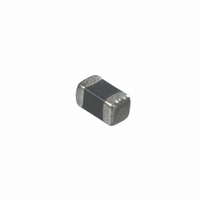
PRG18BB471MS1RB Murata Electronics North America, PRG18BB471MS1RB Datasheet

PRG18BB471MS1RB
Manufacturer Part Number
PRG18BB471MS1RB
Description
THERMISTOR
Manufacturer
Murata Electronics North America
Series
PRG18BBr
Specifications of PRG18BB471MS1RB
Voltage - Max
24V
Current - Max
60mA
Current - Hold (ih) (max)
10mA
Current - Trip (it)
21mA
Package / Case
0603 (1608 Metric)
Lead Free Status / RoHS Status
Lead free / RoHS Compliant
R Min/max
-
Time To Trip
-
No.
10
(*) Measure resistance after the test by applying voltage of less than 1.5Vdc by a direct current of less than 10mA after product is left at 25±2°C for 2 hours.
Above mentioned soldering in "4. Adhesive Strength" and "5. Vibration" is done under the following conditions at our site.
1
2
3
4
5
6
7
8
9
Specifications and Test Methods
PRG18/21BB Series
#Glass-Epoxy PC board
#Standard land dimension
#Standard solder paste
#Standard solder profile
Above conditions are mentioned in Notice.
Operating Temp.
Resistance Value (at 25°C)
Withstanding Voltage
Adhesive Strength
Vibration
Solderability
Solder-heatability
Temperature Cycling
Humidity Test
High Temperature
Load Test
Item
-10 to 60°C
The resistance value should be within the specified
tolerance.
Without damage
There is no exfoliation sign of electrode.
Normal appearance
Resistance change: not to exceed ±20% (*)
Min. 75% electrode is covered with new solder.
Resistance change: not to exceed ±20% (*)
Normal appearance
Resistance change: not to exceed ±20% (*)
Normal appearance
Resistance change: not to exceed ±20% (*)
Normal appearance
Resistance change: not to exceed ±20% (*)
Normal appearance
Resistance change: not to exceed ±20% (*)
Rating Value
Temperature range with maximum voltage applied to PTC.
After applying maximum operating voltage for 3 mins. and
leaving for 2 hrs. in 25°C, measured by applying voltage of less
than 1.5Vdc (by a direct current of less than 10mA).
We apply 120% of the maximum operating voltage to PTC by
raising gradually for 180±5 secs. at 25°C. (A protective resistor
is to be connected in series, and the inrush current through
PTC must be limited below maximum rated value.)
EIAJ ET-7403 term 9
Soldered PTC to PCB and add the force of 5.0N in the direction
as shown below.
JIS C 5102 term 8.2
JIS C 5102 term 8.4
JIS C 5102 term 9.3
Times: 5 cycles
JIS C 5102 term 9.5
40±2°C, 90-95%RH leave for 500±4 hrs.
JIS C 5102 term 9.10
60±3°C (in air), PTC is applied maximum operating voltage for 1.5
hrs. on and 0.5 hrs. off. This cycle is repeated for 1000±10 hrs.
Soldered PTC to PCB
Vibration: A 10-55-10Hz (1 min.)
Width: 1.5mm
Vibrate for 2 hrs. in each of 3 mutually perpendicular planes
for a total of 6 hrs.
Solder: Sn 63%/Pb 37% (or 60/40%)
Solder temp: 230±5°C
Soaking time: 3±0.5 s.
Soaking position: Until a whole electrode is soaked
Solder: Sn 63%/Pb 37% (or 60/40%)
Flux: Solder paste containing less than 0.2wt% of chlorine.
Preheating: 150±5°C 3 mins.
Peak temp.: 260±5°C 10±5 s. (reflow)
PCB: Glass Epoxy PCB (JIS C 6484)
Step
1
2
3
4
Room temp.
Room temp.
Temp. (°C)
+85 +3, -0
-20 +0, -3
Method of Examination
PTC
F
Time (min.)
10-15
10-15
30
30
Glass Epoxy PCB
F=5.0N
F


