H7CX-A114D1-N-DC12-24/AC24 Omron, H7CX-A114D1-N-DC12-24/AC24 Datasheet - Page 11
H7CX-A114D1-N-DC12-24/AC24
Manufacturer Part Number
H7CX-A114D1-N-DC12-24/AC24
Description
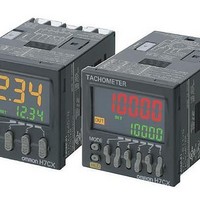
Tachometers 11-pin SPDT 4 Digits 12-24VDC/VAC24
Manufacturer
Omron
Type
1 Stage and Total Preset Counterr
Datasheet
1.H7CX-A-N_AC100-240.pdf
(56 pages)
Specifications of H7CX-A114D1-N-DC12-24/AC24
Frequency Response
50 Hz
Product
Panel Mount Tachometer
Voltage
12 VDC to 24 VDC
Display Type
4 Digit
Accuracy
+/- 0.1 %
Lead Free Status / RoHS Status
Lead free / RoHS Compliant
Other names
DC1224/AC24 H7CXA114D1N H7CXA114D1NDC1224/AC24


H7CX-AD-N/-ASD-N/-AWSD-N/-A4D-N/-A4SD-N/-A4WSD-N (Flush Mounting Models)
H7CX-A11-N/-A11S-N/-A11D1-N/-A11SD1-N/-A114-N/-A114S-N/-A114D1-N (Flush Mounting/Surface Mounting Models)
Dimensions with Flush Mounting Adapter
H7CX-A-N/-AS-N/-AW-N/-AWS-N/-AWD1-N/-AWSD1-N/-A4-N/-A4S-N/-A4W-N
(Provided with Adapter and Waterproof Packing)
H7CX-AD-N/-ASD-N/-AWSD-N/-A4D-N/-A4SD-N/-A4WSD-N
(Provided with Adapter and Waterproof Packing)
H7CX-A11-N/-A11S-N/-A11D1-N/-A11SD1-N/-A114-N/-A114S-N/-A114D1-N
(Adapter and Waterproof Packing Ordered Separately)
58
58
58
Y92S-29 (order separately)
Waterproof Packing
48
48
48
Y92S-29 (provided)
Waterproof Packing
Y92S-29 (provided)
Waterproof Packing
(51)
(51)
(51)
7.5
7.5
7.5
48
48
48
48
Panel
Panel
Panel
57.5
Y92F-30 (provided)
Flush Mounting Adapter
6
6
Y92F-30 (provided)
Flush Mounting Adapter
Y92F-30 (order separately)
Flush Mounting Adapter
76.5
89.9
Note: M3.5 terminal screw (effective length: 6 mm)
59
63.7
44.8
14.4
44.8
44.8
44.8
Panel Cutouts
Panel cutouts are as shown below. (according
to DIN43700).
Note: 1. The mounting panel thickness
Dimensions with Front
Connecting Socket
* These dimensions depend on the kind of DIN Track.
(Reference value)
2. To allow easier operation, it is
3. It is possible to mount counters
60 min.
P2CF-11(-E) Front Connecting Socket
With Y92A-48F1 attached.
With Y92A-48 attached.
A={48n 2.5+(n 1) 4}
103.2*
A=(51n 5.5)
should be 1 to 5 mm.
recommended that Adapters be
mounted so that the gap between
sides with hooks is at least 15 mm
(i.e., with the panel cutouts
separated by at least 60 mm).
side by side, but only in the
direction without the hooks. If they
are mounted side-by-side, water-
resistance will be lost.
15 min.
45
+ 0.6
n Units mounted
0
A=(48n 2.5)
side by side
(order separately)
H7CX-A@-N
45
A
H7CX
-A11@
+ 0.6
+1
0
0
60 min.
+1
0
+1
0
100.9
11