I200S Fluke, I200S Datasheet
I200S
Manufacturer Part Number
I200S
Description
Clamp Multimeters & Accessories 200 AMP CLAMP VOL
Manufacturer
Fluke
Type
Current Clampr
Datasheet
1.I200.pdf
(2 pages)
Specifications of I200S
Accuracy
+/- 2 %
Frequency
100 KHz
Voltage
240 A
Ranging
240 A
Features
2 meter cable
Bandwidth
40 to 10 kHz @ -1.5 dB, 40 kHz @ -3 dB
Conductor Size
0.8 in. (Max)
Current, Rating
240 A
Dimensions
5.3 x 2 x 1.2 in.
Jaw Opening
0.82 in.
Standards
CE Marked
Temperature, Operating
-10 to 55 °C
Voltage, Rating
600 VAC
Two Ranges
20 A & 200A, 10 or 100 mV/ Amp output
Lead Free Status / RoHS Status
Lead free / RoHS Compliant
Other names
664760


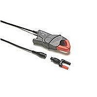
Introducing the i200/i200s
The i200 is a single range 200A clamp-on AC Current Clamp with
current output via safety shrouded banana plugs.
The i200s is a dual range 20A and 200A clamp-on AC Current
Clamp with voltage output via a safety insulated BNC connector.
A dual banana to BNC adapter is supplied to allow the i200s to be
connected to multimeters with banana input.
Unpacking
The following items should be included in your Current Clamp box:
•
•
•
Check the contents of the shipping box for completeness. If
something in the box has been damaged or missing, contact your
distributor or the nearest FLUKE sales or service office
immediately.
Using the Current Clamp Safely
•
•
•
•
•
PN 4822 872 00934
July 1998, Rev. 4, 08/01
© 1998, 1999, 2001 Fluke Corporation.
All rights reserved.
Printed in France
All product names are trademarks of their respective companies.
Current Clamp
Dual Banana to BNC Adapter model PM9081 (only with i200s)
Instruction Sheet (this paper)
To prevent electric shock or fire and personal injury,
carefully read all safety information before attempting
to operate the Current Clamp and follow these
procedures:
Do not use the clamp on circuits rated higher than 600V in
Installation Category III (See "Specifications", subsection
“SAFETY”.) Use caution when clamping around uninsulated
conductors or bus bars.
Do not use a clamp that is cracked, damaged, or has a
defective cable. Such clamps should be made inoperative by
taping the clamp shut to prevent operation.
Check the magnetic mating surfaces of the clamp jaws; these
should be free of dust, dirt, rust, and other foreign matter.
Keep your fingers off the clamp jaws.
Keep your fingers behind the safety barrier as shown in
figure1.
AC Current Clamp
Warning
i200/i200s
Instruction Sheet
®
In this Users Manual, a Warning identifies conditions and actions
that pose hazard(s) to the user. A Caution identifies conditions and
actions that may damage the current clamp. International electrical
symbols used are explained below.
Figure 1. Safely holding the Current Clamp
See explanation in
manual
Double Insulation
(Protection class)
Safety barrier
Conformité
Européenne
Earth
Specifications
SAFETY
ELECTRICAL SPECIFICATIONS
20A Range (i200s only)
200A Range
Measuring range
Maximum current
Crest factor
Maximum non-destructive
CE Conformity
All Electrical Specifications are valid at the following reference
conditions:
Measuring range
Maximum current
Crest factor *)
Maximum non-destructive
current
Output signal
Output impedance
Basic accuracy
Additional error:
Phase shift
current
Output signal
Output impedance
Basic accuracy
Additional error:
Phase shift
•
•
•
•
•
•
•
•
48 Hz to 65 Hz
40 Hz to 48 Hz and
65 Hz to 1 kHz
1 kHz to 10 kHz
Continuous
10 min ON
/30 min OFF
48 Hz to 65 Hz
40 Hz to 48 Hz and
65 Hz to 1 kHz
1 kHz to 10 kHz
0.5A to 10A
10A to 40A
40A to 100A
100A to 240A
Ambient temperature
Relative Humidity
Frequency
Continuous external field
Load impedance
The current may not contain any DC component
No influence from adjacent currents
The conductor must be centered within the jaw aperture
Input jaws
output floating voltage to
ground
100A to 240A
and
40A to 100A
0.5A to 10A
10A to 40A
i200
+ < 3%
+ < 12%
Unspecified
≤ 5 °
≤ 3 °
≤ 2.5 °
0.5 to 240A
240A
< 3
1 mA/A
-
≤ 3% + 0.5A
≤ 2.5% + 0.5A
≤ 2% + 0.5A
≤ 1% + 0.5A
@ Frequency ≤ 1 kHz and
0.1 to 24A
24A
< 3
200A (Frequency ≤ 1 kHz and
crest factor < 3)
100 mV/A
≤ 20 Ω @ 1 kHz
≤ 2% + 0.5A
+ < 10%
+ < 15%
Unspecified
23±3°C (73±3°F)
20 to 75%
48 to 65 Hz
< 40 A/m
i200: 0.2 Ω …15 Ω
i200s: >1 M Ω // 100 pF
Meets requirement of:
for 600V CAT III,
pollution degree 2.
Meets requirement of:
crest factor < 3
EN/IEC61010-1
EN/IEC61010-2-032
UL3111,
EN 50081-1, EN 50082-2
200A
240A
i200s
+ < 3%
+ < 12%
Unspecified
≤ 6 °
≤ 4 °
≤ 3 °
0.5 to 240A
240A
< 3
10 mV/A
≤ 10 Ω @ 1 kHz
≤ 3.5% + 0.5A
≤ 3% + 0.5A
≤ 2.5% + 0.5A
≤ 1.5% + 0.5A
All ranges
*) This is the maximum permissible ratio between the peak value
of a superimposed transient and the ac rms value.
GENERAL
Instrument Compatibility
The i200s is compatible with any Fluke ScopeMeter test tool,
Power Harmonics Analyzer, Oscilloscope, Multimeter, or other
voltage measurement device that has the following features:
•
•
•
•
The i200 is compatible with any Fluke Multimeter or any other
current measurement device that has the following features:
•
•
•
•
Load on output
Load Influence
Bandwidth
Additional errors
Clamp Dimensions
Protection index
Jaw Opening
Height of open Jaws
Maximum conductor size
Weight
Cable length
Temperature
Relative Humidity
Altitude
EMC
Operating
Non-operating
Operating
Operating
Non-operating
BNC input connector. The Dual Banana to BNC Adapter
included in the package, can be used to connect to standard
inputs on multimeters. For the 120 series ScopeMeters, use
the BB120 Shielded Banana to BNC Adapter.
Input accuracy of 2% or better to take full advantage of the
accuracy of the Current Clamp.
Input impedance of greater than or equal to 1 MΩ, and for full
bandwidth and accuracy, a maximum input capacity of 100 pF.
A passband of more than four times the frequency of the
waveform to be measured.
Banana inputs.
Input accuracy of 2% or better to take full advantage of the
accuracy of the Current Clamp.
Input impedance of 0.2Ω …15Ω
A passband of more than four times the frequency of the
waveform to be measured.
With temperature
With position of
conductor in the
clamp aperture
With adjacent
conductors
-1.5 dB
-3dB
i200
i200s
i200
0.2...15 Ω
Current: < 1%
Phase: < 1°
40 Hz to 10 kHz
40 kHz
135 x 50 x 30 mm
(5.3 x 2 x 1.2 in)
IP40
21 mm (0.82 in)
69 mm (2.7 in)
∅ 20 mm (0.8 in) or
busbar 20 x 5 mm (0.8 x 0.2 in)
180 g (6.4 oz)
1.5 m (5.9 in)
2m (7.9 in)
-10 to +55°C (+14 to +131°F)
-40 to + 70°C (-40 to +158°F)
85%, up to +30°C (+86°F)
75%, up to +55°C (+131°F)
to 2000 m (6500 ft)
to 12000 m (40000 ft)
EN 50081-1
EN 50082-2
≤ 15 mA / A @ 50 Hz
≤ 0.5 % @ 50 Hz
≤ 0.15 % / 10 K
i200s
>1 MΩ // < 100 pF
-
-
40 Hz to 10 kHz
40 kHz
(3V/m, 2.74V/yd)
I200S Summary of contents
Page 1
... International electrical Clamp with voltage output via a safety insulated BNC connector. symbols used are explained below. A dual banana to BNC adapter is supplied to allow the i200s to be connected to multimeters with banana input. Unpacking The following items should be included in your Current Clamp box: • ...
Page 2
... Observe the current value and waveform on the instrument’s display. 7. i200s: If desired, select a lower range on the Current Clamp and set the corresponding sensitivity (mV/A setting) on the ScopeMeter test tool or oscilloscope. Example with multimeter for i200: Current Clamp sensitivity = 1 mA/A. Multimeter displays 168 mA. ...