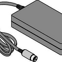
TR25D-01Y-14A03 Cincon, TR25D-01Y-14A03 Datasheet

TR25D-01Y-14A03
Manufacturer Part Number
TR25D-01Y-14A03
Description
Plug-In AC Adapters 25W 90-264VAC 3.3/5VDC 4/3A
Manufacturer
Cincon
Datasheet
1.TR25D-04Y-14A03.pdf
(1 pages)
Specifications of TR25D-01Y-14A03
Mounting Style
Desktop
Input Voltage (nominal)
90 VAC to 264 VAC
Number Of Outputs
2
Output Power Rating
25 W
Output Voltage (channel 1)
3.3 V
Output Current (channel 1)
3 A
Output Voltage (channel 2)
5 V
Output Current (channel 2)
2 A
Dc Output Connector
6 Pin DIN
Dc Output Cord Length
1800 mm
Ac Plug Included/required
Required
Commercial/medical
Commercial
Lead Free Status / RoHS Status
Lead free / RoHS Compliant
T R 2 5 D
S
TR25D-0XY - X
Model No.
TR25D-01Y
TR25D-02Y
TR25D-03Y
TR25D-04Y
25W SWITCHING
ADAPTER
DUAL OUTPUTS
• Universal Input Range 90-264VAC
• Meets EN55022 Class B and
MODEL
CISPR/FCC Class B, Conducted
DIN Type
1 : 5Pin Din Plug
2 : 6Pin Mini Din Plug
3 : 6Pin Din Plug
4 : 4Pin Din Plug
5 : Sub-D 9Pin
6 : Open end
E
+3.3V(V1)
+12V(V2)
+15V(V2)
+24V(V2)
VOLTAGE
OUTPUT
(VOLTS)
+5V(V2)
+5V(V1)
+5V(V1)
+5V(V1)
Ordering information
XX
Pin Assignment
1 : Pin1,2,4 :GND Pin3 : V1 Pin5 : V2
2 : Pin1,3:GND Pin2:V1 Pin4:V2
3 : Pin1,2:GND Pin3,5:V2 Pin4,6:V1
4 : Pin1,2:GND Pin3:N.C. Pin4:V1 Pin5:V2
5 : Pin1,2:GND Pin3:N.C. Pin4,6:V1 Pin5:V2
6 : Pin1,2:GND Pin3:V1 Pin4:N.C. Pin5:V2
7 : Pin3,4:V1 Pin1,2:V2
8 : NO Pin
9 : Pin1:V1 Pin2:V2 Pin3:GND Pin4,5:N.C.
11 : Pin1,4:+12V P2,5:GND Pin3,6:+5V
OUTPUT CURRENT (AMPS)
MIN.
0.13
R
0.3
0.2
0.2
0.2
0.1
0.2
0.1
RATED MAX.
1.3
0.6
3
2
2
2
1
2
I
X
OVP Option
A : Without OVP Option
E : With OVP Option
1.5
4
3
3
2
3
3
1
(AMPS)
E
PEAK
XX
DC Cable Length and Type
01 : 720mm
02 : 1200mm
03 : 1800mm
05 : 1200mm with Ferrite Core
49 : 1800mm with Ferrite Core
* 18AWG
1.5
5
4
4
3
4
2
4
1
RIPPLE
Features
(mV)
120
150
240
S
50
50
50
50
50
2
, P-P
• Continuous Short Circuit Protection
• Over Voltage Protection (Option)
REGULATION
TOTAL
±7%
±5%
±5%
±5%
±5%
±5%
±5%
±5%
3
O/P POWER
20W
25W
25W
25W
MAX.
FREQUENCY
SWITCHING
55KHz Typ.
55KHz Typ.
55KHz Typ.
55KHz Typ.
65% min.
65% min.
65% min.
65% min.
%EFF.
0.13A(V2)
0.3A(V1)
0.2A(V2)
0.2A(V1)
0.2A(V1)
0.1A(V2)
0.2A(V1)
0.1A(V2)
LOAD
MINI.
Typical at 25˚C, nominal line and 75% load, unless otherwise Specified.
INPUT SPECIFICATIONS:
Voltage ........................................................................................90 ~ 264Vac
Frequency .......................................................................................47 to 63Hz
Inrush Current..................................................................50A max. @ 240Vac
Conducted EMI.............................................................. CISPR/FCC Class B
Isolation ............................................................ lnput to output =4,242VDC
Leakage Current........................................................................1.5mA max.
OUTPUT SPECIFICATIONS:
Holdup Time ..................................................................16mS typ. @115Vac
Short Circuit Protection ..............................................................Continuous
Over Voltage Protection ...................................................................Option
ENVIRONMENTAL CHARACTERISTICS:
Operating Temperature ................................................................. 0 ~ 40˚C
Storage Temperature ...................................................................-20 ~ 85˚C
Cooling..........................................................................Natural Convection
MECHANICAL CHARACTERISTICS:
Dimensions ..........132.00 x 58.00 x 30.00mm(5.197 x 2.283 x 1.181 Inches)
Weight ..............................................................................305g (0.67Pounds)
AC Inlet........................................................................................ IEC320/C14
Mechanical Specification
All Dimensions In Inches(mm)
Tolerance
Inches: x.xxx= ±0.02
Millimeters: x.xx= ±0.5
Specifications
NOTE:
1. Peak output current (total output power must less than 32W) lasting less than one
2. Add a 0.1µF ceramic capacitor and a 10µF E.L. capacitor to the output cable.
3. Total regulation is defined as the static output regulation at 25˚C, including initial
DC plug & pin assignment (CUSTOM DESIGN IS AVAILABLE)
Y:SEC-GND is isolated from AC-GND.
100%
80%
60%
40%
20%
minute with duty factor less than 5%. During peak loading, output voltage may
exceed total regulation limits.
Peak to peak and RMS metering equipment shall have a 20 MHz response with
probes and cables maintaining frequency response from 200Hz to 100MHz bandwidth.
Output ripple and spikes are measured directly at the output terminals of the power
supply without the use of the probe ground clip.
tolerance, line voltage within stated limits. And load currents within stated limits,
but when V1 exceed rated load, the total regulation will be ±10%.
0%
OUTPUT NO.
PIN1
PIN2
PIN3
PIN4
PIN5
PIN6
0
TR25D Series Derating Curve
20LFM(Natural Convection)
10
TR25D-XX
GND
GND
NC
V1
V2
V1
Ambient Temperature(˚C)
20
30
DIN PLUG
(5P 180°)
-14A02
40
50
DIN PLUG
(6P 240°)
-35A02
60


