LSN2-T/22-D12-C Murata Power Solutions Inc, LSN2-T/22-D12-C Datasheet - Page 6
LSN2-T/22-D12-C
Manufacturer Part Number
LSN2-T/22-D12-C
Description
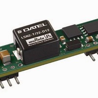
DC/DC Converters & Regulators 12Vin 0.8-5Vout 22A 112W NonIso DOSA-SIP
Manufacturer
Murata Power Solutions Inc
Series
LSN2r
Datasheet
1.LSN2-T22-D12-C.pdf
(13 pages)
Specifications of LSN2-T/22-D12-C
Output Power
110 W
Input Voltage Range
8.3 V to 14 V
Input Voltage (nominal)
12 V
Number Of Outputs
1
Output Voltage (channel 1)
0.8 V to 5 V
Output Current (channel 1)
22 A
Package / Case Size
SIP
Output Type
Low Voltage Selectable
Output Voltage
0.8 V to 5 V
Product
Non-Isolated / POL
Lead Free Status / RoHS Status
Lead free / RoHS Compliant
Other names
LSN2-T/22-D12-C


The internal 10.5: resistor between +Sense and +Output (see Figure 1)
serves to protect the sense function by limiting the output current fl owing
through the sense line if the main output is disconnected. It also prevents
output voltage runaway if the sense connection is disconnected.
Note: If the sense function is not used for remote regulation, +Sense
must be tied to +Output at the DC/DC converter pins.
Remote On/Off Control
The input-side remote On/Off Control is an external input signal available in
either positive (no suffi x) or negative (“N” suffi x) polarity. Normally this input
is controlled by the user’s external transistor or relay. With simple external
circuits, it may also be selected by logic outputs. Please note however that
the actual control threshold levels vary somewhat with the PWM supply and
therefore are best suited to “open collector” or “open drain” type logic. The
On/Off control takes effect only when appropriate input power has been
applied and stabilized (approximately 7msec).
For positive polarity, the default operation leaves this pin open (unconnected)
or HIGH. The output will then always be on (enabled) whenever appropriate
input power is applied. Negative polarity models require the On/Off to be
grounded to the –Input terminal or brought LOW to turn the converter on.
To turn the converter off, for positive polarity models, ground the On/Off
control or bring it LOW. For negative polarity, raise the On/Off at least to +2.5V
to turn it off.
Dynamic control of the On/Off must be capable of sinking or sourcing the
control current (approximately 1mA max.) and not overdrive the input greater
than the +V
activating the On/Off control. Be aware that a delay of several milliseconds
occurs (see specifi cations) between activation of the control and the resulting
change in the output.
Power-up sequencing
If a controlled start-up of one or more LSN2 Series DC/DC converters is
required, or if several output voltages need to be powered-up in a given
sequence, the On/Off control pin can be driven with an external open collector
device as per Figure 4.
Leaving the input of the on/off circuit closed during power-up will have the
output of the DC/DC converter disabled. When the input to the external open
collector is pulled high, the DC/DC converter's output will be enabled.
Figure 4. On/Off Control Using An External Open Collector Driver
IN
power input. Always wait for the input power to stabilize before
www.murata-ps.com
Output Overvoltage Protection
LSN2 SIP Series DC/DC converters do not incorporate output overvoltage pro-
tection. In the extremely rare situation in which the device’s feedback loop is
broken, the output voltage may run to excessively high levels (V
is absolutely imperative that you protect your load against any and all possible
overvoltage situations, voltage limiting circuitry must be provided external to
the power converter.
Output Overcurrent Detection
Overloading the power converter's output for an extended time will invariably
cause internal component temperatures to exceed their maximum ratings and
eventually lead to component failure. High-current-carrying components such
as inductors, FET's and diodes are at the highest risk. LSN2 SIP Series DC/DC
converters incorporate an output overcurrent detection and shutdown function
that serves to protect both the power converter and its load.
If the output current exceeds it maximum rating by typically 50% or if the
output voltage drops to less than 98% of it original value, the LSN2's internal
overcurrent-detection circuitry immediately turns off the converter, which then
goes into a "hiccup" mode. While hiccupping, the converter will continuously
attempt to restart itself, go into overcurrent, and then shut down. Once the
output short is removed, the converter will automatically restart itself.
Output Reverse Conduction
Many DC/DC's using synchronous rectifi cation suffer from Output Reverse
Conduction. If those devices have a voltage applied across their output before
a voltage is applied to their input (this typically occurs when another power
supply starts before them in a power-sequenced application), they will either
fail to start or self destruct. In both cases, the cause is the "freewheeling" or
"catch" FET biasing itself on and effectively becoming a short circuit.
LSN2 SIP DC/DC converters do not suffer from Output Reverse Conduction.
They employ proprietary gate drive circuitry that makes them immune to
moderate applied output overvoltages.
Thermal Considerations and Thermal Protection
The typical output-current thermal-derating curves shown below enable
designers to determine how much current they can reliably derive from each
model of the LSN2 SIPs under known ambient-temperature and air-fl ow con-
ditions. Similarly, the curves indicate how much air fl ow is required to reliably
deliver a specifi c output current at known temperatures.
22A Selectable-Output DC/DC Converters
Figure 5. Inverting On/Off Control
25 Jun 2010
LSN2-T/22-D12
MDC_LSN2-T/22-D12_B03Δ
Non-isolated, DOSA-SIP,
email: sales@murata-ps.com
OUT
= V
Page 6 of 13
IN
). If it
Related parts for LSN2-T/22-D12-C
Image
Part Number
Description
Manufacturer
Datasheet
Request
R

Part Number:
Description:
DC/DC Converters & Regulators 12Vin 0.8-5Vout 22A 112W Neg polarity
Manufacturer:
Murata Power Solutions Inc
Datasheet:

Part Number:
Description:
DC/DC Converter
Manufacturer:
Murata Power Solutions Inc
Datasheet:
Part Number:
Description:
DC/DC Converter
Manufacturer:
Murata Power Solutions Inc
Datasheet:

Part Number:
Description:
DC/DC Converters & Regulators 12Vin 0.8-5Vout 30A 150W Power Good Out
Manufacturer:
Murata Power Solutions Inc
Datasheet:
Part Number:
Description:
DC/DC Converters & Regulators 12Vin 0.8-5Vout 30A 150W Neg polarity
Manufacturer:
Murata Power Solutions Inc
Part Number:
Description:
DC/DC Converters & Regulators 12Vin 0.8-5Vout 30A 150W PowerGood NegPl
Manufacturer:
Murata Power Solutions Inc

Part Number:
Description:
CONV DC/DC 30W 6A 0.75-5V SIP
Manufacturer:
Murata Power Solutions Inc
Datasheet:

Part Number:
Description:
CONV DC/DC 33W 10A .75-3.3V SIP
Manufacturer:
Murata Power Solutions Inc
Datasheet:

Part Number:
Description:
CONV DC/DC 50W 10A 0.75-5V SIP
Manufacturer:
Murata Power Solutions Inc
Datasheet:

Part Number:
Description:
CONV DC/DC 19.8W 6A .75-3.3V SIP
Manufacturer:
Murata Power Solutions Inc
Datasheet:

Part Number:
Description:
Transformers 5Vin 5Vout 200mA 4000Vdc 1:1.33 turn
Manufacturer:
Murata Power Solutions Inc
Datasheet:

Part Number:
Description:
POWER SUPPLY
Manufacturer:
Murata Power Solutions Inc
Datasheet:

Part Number:
Description:
DPM LED MINI 2VDC 3.5DIG LP RED
Manufacturer:
Murata Power Solutions Inc
Datasheet:

Part Number:
Description:
CONV DC/DC 1W 5VIN 5VOUT SIP SGL
Manufacturer:
Murata Power Solutions Inc
Datasheet:

Part Number:
Description:
CONV DC/DC 1W 5VIN 3.3V SIP SGL
Manufacturer:
Murata Power Solutions Inc
Datasheet: