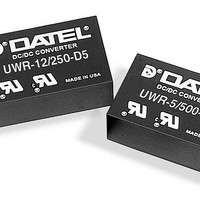
UWR-5/500-D12-C Murata Power Solutions Inc, UWR-5/500-D12-C Datasheet - Page 2

UWR-5/500-D12-C
Manufacturer Part Number
UWR-5/500-D12-C
Description
DC/DC Converters & Regulators 3W 12V to 5V 500mA
Manufacturer
Murata Power Solutions Inc
Type
Step Downr
Series
UWRr
Datasheet
1.UWR-12250-D5-C.pdf
(4 pages)
Specifications of UWR-5/500-D12-C
Output Power
3 W
Input Voltage Range
9 V to 18 V
Input Voltage (nominal)
12 V
Number Of Outputs
1
Output Voltage (channel 1)
5 V
Output Current (channel 1)
500 mA
Isolation Voltage
1 KV
Package / Case Size
DIP
Package
8PDIP
Output Current
0.5 A
Output Voltage
5 V
Input Voltage
12 V
Switching Regulator
Yes
Product
Isolated
Lead Free Status / RoHS Status
Lead free / RoHS Compliant
Other names
UWR-5/500-D12-C
Soldering Guidelines
Murata Power Solutions recommends the specifications below when installing these
converters. These specifications vary depending on the solder type. Exceeding these
specifications may cause damage to the product. Be cautious when there is high atmo-
spheric humidity. We strongly recommend a mild pre-bake (100° C. for 30 minutes). Your
production environment may differ; therefore please thoroughly review these guidelines
with your process engineers.
For Sn/Ag/Cu based solders:
Maximum Preheat Temperature
Maximum Pot Temperature
Maximum Solder Dwell Time
For Sn/Pb based solders:
Maximum Preheat Temperature
Maximum Pot Temperature
Maximum Solder Dwell Time
*Contact Murata Power Solutions for availability
UWR-12/250-D12
UWR-15/200-D48
UWR-5/500-D5
UWR-5/500-D12
UWR-5/500-D48
UWR-12/250-D5
UWR-12/250-D48
UWR-15/200-D12
Wave Solder Operations for through-hole mounted products (THMT)
PERFORMANCE SPECIFICATIONS AND ORDERING GUIDE
UWR-15/200-D5
Output Configuration:
PART NUMBER STRUCTURE
Typical at T
Ripple/Noise (R/N) measured over a 20MHz bandwidth.
10% to 100% load.
Nominal line voltage, no-load/full-load conditions.
The models with strikethroughs are obsolete. Please contact Murata Power Solutions for alternate solutions.
U = Unipolar
Model
Wide Range Input
A
= +25°C under nominal line voltage and full-load conditions unless otherwise noted.
Nominal Output Voltage:
5, 12 or 15 Volts
U WR
(Volts)
V
12
12
12
15
15
15
OUT
5
5
5
-
5
(mA, Max.)
/
I
500
500
500
250
250
250
200
200
200
OUT
500
115° C.
270° C.
7 seconds
105° C.
250° C.
6 seconds
-
Maximum Output Current
in mA
D48
Input Voltage Range:
R/N (mVp-p)
Typ.
75
75
75
75
75
75
75
75
75
D5 = 4.5-9 Volts (5V nominal)
D12 = 9-18 Volts (12V nominal)
D48 = 18-72 Volts (48V nominal)
www.murata-ps.com
Output
-
C
Max.
120
120
150
150
150
150
150
150
150
RoHS-6 hazardous
substance compliant*
Regulation (Max.)
±0.2%
±0.2%
±0.2%
±0.5%
±0.5%
±0.5%
±0.5%
±0.5%
±0.5%
Line
±0.5%
±0.5%
±0.5%
±0.5%
±0.5%
±0.5%
±0.5%
±0.5%
±0.5%
Load
MECHANICAL SPECIFICATIONS
All dimension in Inches (mm)
V
(Volts)
IN
12
48
12
48
12
48
Nom.
5
5
5
0.020 ±0.002 DIA.
Pin
(0.508 ±0.051)
1
2
3
4
5
6
7
8
I/O Connectiions
PLASTIC CASE WITH AN INSULATED BASE
(Volts)
Function P1
Range
18-72
18-72
18-72
Input
4.5-9
4.5-9
4.5-9
9-18
9-18
9-18
Common
Common
+Output
+Output
+Input
+Input
Technical enquiries email: sales@murata-ps.com, tel:
–Input
–Input
3 Watt, Single Output DC/DC Converters
(11.43)
(2.54)
0.100
0.45
18/694
25/282
30/800
25/340
30/811
25/340
11/78
11/78
I
(mA)
6/65
IN
3 4
1 2
BOTTOM VIEW
Dimensions are in inches (mm shown for ref. only).
Case C1
(15.24)
0.600
(31.75)
1.25
Components are shown for reference only.
Tolerances (unless otherwise specified):
.XX ± 0.02 (0.5)
.XXX ± 0.010 (0.25)
Angles ± 2˚
Min.
70%
70%
75%
72%
72%
76%
72%
72%
76%
MDC_UWR3W Series.B03 Page 2 of 4
7
5
Efficiency
Full Load
8
6
Third Angle Projection
UWR Series
(15.24)
STANDOFFS
0.600
(2.54)
0.10
(5.08)
0.200
0.025
(0.64)
(4.57)
0.18
72%
72%
77%
75%
74%
80%
74%
76%
78%
Typ.
0.15 MIN
(20.32)
(3.81)
0.80
+1 508 339 3000
Package
Pinout)
(Case/
C1, P1
C1, P1
C1, P1
C1, P1
C1, P1
C1, P1
C1, P1
C1, P1
C1, P1


