28040 Parallax Inc, 28040 Datasheet - Page 5
28040
Manufacturer Part Number
28040
Description
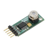
Board Mount Temperature Sensors Infrared Thermometer 90 Deg Mod MLX90614
Manufacturer
Parallax Inc
Datasheet
1.28040.pdf
(10 pages)
Specifications of 28040
Temperature Threshold
+ 380 C
Package / Case
SIP-5
Digital Output - Number Of Bits
16 bit
Supply Voltage (max)
5 V
Description/function
Temperature Sensor
Maximum Operating Temperature
+ 70 C
Minimum Operating Temperature
0 C
Supply Current
20 mA
Lead Free Status / RoHS Status
Lead free / RoHS Compliant


"W"
SEROUT pin, baudrate, [0,"!TEMW",slaveaddr,commandaddr,lowdatabyte,highdatabyte]
The "W" command will write the data into the module’s specified EEPROM address. This is permanent
until rewritten and requires a power cycle on the module. Available command EEPROM addresses are:
*count word x 0.02 = K
Example:
This command always writes four bytes. The example will write a new slave address ($1A) in an EEPROM
location ($2E) and set a sleep mode (“z”) for continuous data output. A 50 ms delay lets the module
erase and write to sensor EEPROM before advancing to the next PBASIC statement.
"C"
"c"
SEROUT pin, baudrate, [0,"!TEMC",slaveaddr, commandaddr]
The "C" command will cause the module to read object temperature data continuously. No data will be
serially transmitted back. The "c" command will cause the module to serially transmit sensor data
continuously. It is necessary to read data continuously to check for over alarm setting. “C” is the default
command on power up. To set the default command a “C” or “c” can be written into the high byte of the
slave address EEPROM ($2E).
Example:
The example reads and transmits the slave address ($5A), object temperature low and high data bytes,
and PEC byte stored in the sensor RAM. Note that the “TEM” string indicates the start of the data output
and must be included in data readings. This allows you to differentiate multiple sensors on a single bus.
Note: Care must be taken in setting multiple sensors up for continuous output. Be sure your interval
settings are such that multiple sensors are not transmitting at the same time or you will experience data
collision making the values unreadable.
This example reads the slave address ($5A), object temperature low and high data bytes, and PEC byte
stored in the sensor RAM ($07) but does not transmit any data.
Copyright © Parallax Inc.
Address
SEROUT pin, baudrate,[0,"!TEMW",$5A,$2E,$1A,"z"]
PAUSE 50
SEROUT pin, baudrate,[0,"!TEMc",$5A,$07]
Again:
SEROUT pin, baudrate,["!TEMC",$5A,$07]
$2E
$20
$21
SERIN
GOTO
Write Sensor Data
Set Sensor for Continuous Data Reading
Set Sensor for Continuous Data Reading and Output
pin, baudrate,[Wait{"TEM"),slave,lowbyte,highbyte,pec]
AGAIN
and Setup State
Slave Address
Temperature
Read Time
Purpose
Intervals
Alarm
MLX90614 Infrared Thermometer Modules (#28040-28042)
$7F>= Slave address =>$01
count x 10 ms
(non sleep)
Low Byte
'minimum time allowed to write to sensor EEPROM
count word*
“C”, “c”, “Z”, “z”, or “S”
count x 1.15 seconds
High Byte
(sleep)
v2.0 11/18/2008 Page 5 of 8
50 ms non sleep and
1.15 seconds sleep
$5A slave address
(186575 counts)
Default
and “C”
100 °C
Related parts for 28040
Image
Part Number
Description
Manufacturer
Datasheet
Request
R


Part Number:
Description:
Microcontroller Modules & Accessories DISCONTINUED BY PARALLAX
Manufacturer:
Parallax Inc

Part Number:
Description:
BOOK UNDERSTANDING SIGNALS
Manufacturer:
Parallax Inc
Datasheet:


Part Number:
Description:
COMPETITION RING FOR SUMOBOT
Manufacturer:
Parallax Inc
Datasheet:


Part Number:
Description:
TEXT INFRARED REMOTE FOR BOE-BOT
Manufacturer:
Parallax Inc
Datasheet:
Part Number:
Description:
BOARD EXPERIMENT+LCD NX-1000
Manufacturer:
Parallax Inc
Datasheet:

Part Number:
Description:
CONTROLLER 16SERVO MOTOR CONTROL
Manufacturer:
Parallax Inc
Datasheet:

Part Number:
Description:
BASIC STAMP LOGIC ANALYZER
Manufacturer:
Parallax Inc
Datasheet:

Part Number:
Description:
IC MCU 2K FLASH 50MHZ SO-18
Manufacturer:
Parallax Inc
Datasheet: