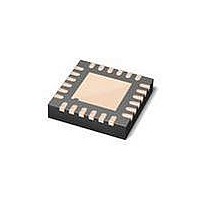
MAX6581TG9A+ Maxim Integrated Products, MAX6581TG9A+ Datasheet - Page 8

MAX6581TG9A+
Manufacturer Part Number
MAX6581TG9A+
Description
Board Mount Temperature Sensors 1 C ACCUR 8-CH TEMP SENSR
Manufacturer
Maxim Integrated Products
Datasheet
1.MAX6581ATG9A.pdf
(24 pages)
Specifications of MAX6581TG9A+
Full Temp Accuracy
+/- 1 C
Package / Case
TQFN-24
Digital Output - Bus Interface
I2C
Digital Output - Number Of Bits
11 bit
Supply Voltage (max)
3.6 V
Supply Voltage (min)
3 V
Description/function
Multichannel Temperature Sensor
Maximum Operating Temperature
+ 125 C
Minimum Operating Temperature
- 40 C
Supply Current
4 uA
Lead Free Status / RoHS Status
Lead free / RoHS Compliant
The MAX6581 is a precision multichannel temperature
monitor that features one local and seven remote tem-
perature-sensing channels with a programmable alert
threshold for each temperature channel and a program-
mable overtemperature threshold for channels 1–7 (see
Figure 1). Communication with the MAX6581 is achieved
through the SMBus serial interface and a dedicated alert
pin (ALERT). The alarm outputs, (OVERT and ALERT)
assert if the software-programmed temperature thresh-
olds are exceeded. ALERT also asserts if the measured
temperature falls below the ALERT low limits. ALERT
typically serves as an interrupt, while OVERT can be
connected to a fan, system shutdown, or other thermal-
management circuitry.
The MAX6581 starts the conversion sequence by
measuring the temperature on channel 1, followed by 2,
local channel, 3–7. The conversion result for each active
channel is stored in the corresponding temperature data
register. No conversion is performed on any channel that
does not have a diode.
Enter software-standby mode by setting the STOP
bit to 1 in the Configuration register. Enter hardware-
standby by pulling STBY low. Software-standby mode
disables the ADC and reduces the supply current to
approximately 4FA. During either software or hardware
standby, data is retained in memory. During hardware
standby, the SMBus interface is inactive. During software
±1°C Accurate 8-Channel Temperature Sensor
8
______________________________________________________________________________________
PIN
21
23
24
—
NAME
DXN1
DXP1
GND
EP
ADC Conversion Sequence
Detailed Description
Low-Power Standby Mode
Ground
Combined Current Source and ADC Positive Input for Channel 1 Remote Diode. Connect DXP1 to
the anode of a remote-diode-connected, temperature-sensing transistor. Leave DXP1 unconnected
or connect to DXN1 if a remote diode is not used. Connect a 100pF capacitor between DXP1 and
DXN1 for noise filtering.
Cathode Input for Channel 1 Remote Diode. Connect the cathode of the channel 1 remote-diode-
connected transistor to DXN1. If the channel 1 remote transistor is a substrate pnp (e.g., on a CPU
die), connect the base of the pnp to DXN1. Leave DXN1 unconnected or connect to DXP1 if a
remote diode is not used. Connect a 100pF capacitor between DXP1 and DXN1 for noise filtering.
Exposed Pad. Connect EP to GND.
standby, the SMBus interface is active and listening for
commands. The timeout is enabled if a START condition
is recognized on SMBus. Activity on the SMBus causes
the supply current to increase. If a standby command is
received while a conversion is in progress, the conver-
sion cycle is interrupted, and the temperature registers
are not updated. The previous data is not changed and
remains available.
The MAX6581 operates at different operating-current
levels depending on how many external channels are in
use and how many of those are in resistance cancella-
tion (RC) mode. The average operating current is:
where:
N
in normal mode.
N
mode.
I
complete series of conversions.
I
during a conversion in normal mode.
I
during a conversion in RC mode.
AV
CC1
CC2
N
R
= the number of remote channels that are operating
= the average operating power-supply current over a
I
= the number of remote channels that are in RC
FUNCTION
AV
= the average operating power-supply current
= the average operating power-supply current
=
N
N
Pin Description (continued)
+ ×
N
2 N
N
+
Operating-Current Calculation
1
R
+
1
I
CC1
+
N
N
+ ×
2 N
2 N
×
R
R
+
1
×
I
CC2


