E2E-X1R5F1 Omron, E2E-X1R5F1 Datasheet - Page 33
E2E-X1R5F1
Manufacturer Part Number
E2E-X1R5F1
Description
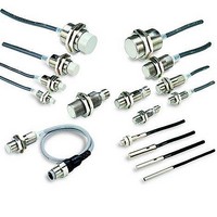
Proximity Sensors PROXIMITY SENSOR
Manufacturer
Omron
Series
E2Er
Specifications of E2E-X1R5F1
Maximum Operating Temperature
+ 85 C
Supply Voltage
30 V
Output Voltage
2 V
Operating Supply Voltage
12 V to 24 V
Minimum Operating Temperature
- 40 C
Maximum Output Current
200 mA
Features
High visibility indicator
Sensing Distance
1.5 mm
Sensor Housing
Cylindrical
Sensor Input
Inductive
Sensing Range Max
1.5mm
Switch Terminals
Cable
Sensor Output
PNP-NO
Proximity Sensor Type
Inductive
Output Type
PNP
Proximity Sensor Sensing Distance
1.5mm
Proximity Sensor Sensing Distance Range
<2mm
Proximity Sensor Switching Mode
NO
Mounting
Panel
Operating Temp Range
-40C to 85C
Operating Temperature Classification
Industrial
Operating Supply Voltage (min)
10V
Operating Supply Voltage (typ)
12/15/18/24V
Operating Supply Voltage (max)
40V
Pin Count
3
Lead Free Status / RoHS Status
Lead free / RoHS Compliant
Lead Free Status / RoHS Status
Lead free / RoHS Compliant, Lead free / RoHS Compliant
Available stocks
Company
Part Number
Manufacturer
Quantity
Price
Company:

Part Number:
E2E-X1R5F1
Manufacturer:
OMRON
Quantity:
1 000
Company:
Part Number:
E2E-X1R5F1
Manufacturer:
OMRON
Quantity:
374
Company:
Part Number:
E2E-X1R5F1-Z
Manufacturer:
EVERLIGHT
Quantity:
52 730


Diagram 20 E2E-X3D@-M1(G)
Diagram 22 E2E-X2Y@-M1
Diagram 24 E2E-X7D@-M1(G)/E2E-X5E@-M1/X5F@-M1
Diagram 26 E2E-X10D@-M1(G)/E2E-X10E@-M1/X10F@-M1
Mounting Hole Dimensions
* D1 Models:
D2/E/Y Models: Operation indicator (red)
42 dia.
21 dia.
21 dia.
* D1 Models: Operation indicator (red), Setting indicator (green)
29 dia.
F
36
D2/E/Y Models: Operation indicator (red)
17
17
24
E2E-X2E@-M1/E2E-X2F@-M1
E2E-X5Y@-M1
E2E-X10Y@-M1
Operation indicator (red), Setting indicator (green)
* D1 Models:
M30 × 1.5
D2/E/F Models: Operation indicator (red)
M12 × 1
M12 × 1
M18 × 1
Dimensions
4
4
5
F (mm)
4
33
38
Operation indicator (red),
Setting indicator (green)
38
Toothed washer
Toothed washer
Toothed washer
43
Toothed washer
48
53
Two clamping nuts
Two clamping nuts
53
Two clamping nuts
10
Two clamping nuts
58
10
10
10
Indicators *
Operation indicator (red)
Indicators*
Indicators*
8.5
M12 × 1
M12 × 1
M12 × 1
+0
M12 × 1
M8
0
.
5
dia. 12.5
M12
+0
0
.
5
dia. 18.5
Diagram 21 E2E-X8MD@-M1(G)
Diagram 23 E2E-X5MY@-M1
Diagram 25 E2E-X14MD@-M1(G)/E2E-X10ME@-M1
Diagram 27 E2E-X20MD@-M1(G)/E2E-X18ME@-M1/
M18
+0
0
.
* D1 Models:
5
D2/E/Y Models: Operation indicator (red)
42 dia.
dia. 30.5
29 dia.
21 dia.
21 dia.
* D1 Models:
D2/E/F Models: Operation indicator (red)
17
24
36
17
* D1 Models:
D2/E/Y Models: Operation indicator (red)
E2E-X5ME@-M1/E2E-X5MF@-M1
X10MF@-M1
E2E-X10MY@-M1
X18MF@-M1
E2E-X18MY@-M1
M30
Operation indicator (red), Setting indicator (green)
+0
14.8 dia.
26.8 dia.
0
9 dia.
9 dia.
.
5
Operation indicator (red), Setting indicator (green)
dia.
M12 × 1
M12 × 1
M18 × 1
Operation indicator (red), Setting indicator (green)
M30 × 1.5
7
7
10
13
4
4
4
33
38
38
43
5
Toothed washer
48
Toothed washer
53
Toothed washer
53
10
Two clamping nuts
58
Two clamping nuts
Two clamping nuts
Toothed washer
10
10
10
Two clamping nuts
Indicators*
Operation indicator (red)
Indicators*
Indicators*
M12 × 1
M12 × 1
M12 × 1
M12 × 1
E2E
33
Related parts for E2E-X1R5F1
Image
Part Number
Description
Manufacturer
Datasheet
Request
R

Part Number:
Description:
E2E-X1C1 W/ ROBOTIC CABLE
Manufacturer:
Omron
Datasheet:
Part Number:
Description:
Proximity Sensors E2E-X5ME1 W/5M CABLE
Manufacturer:
Omron
Datasheet:
Part Number:
Description:
Proximity Sensors Prox Plug In
Manufacturer:
Omron
Datasheet:
Part Number:
Description:
Proximity Sensors PROX E2E-C1C1 W/ 5 M ETER CABLE
Manufacturer:
Omron
Datasheet:
Part Number:
Description:
Proximity Sensors E2E-X1C1 W/ SPECIAL ATTRIBUTES
Manufacturer:
Omron
Datasheet:
Part Number:
Description:
Proximity Sensors PROX E2E-CR8C1 ROBOT CABLE 2M
Manufacturer:
Omron
Datasheet:
Part Number:
Description:
Proximity Sensors E2E-X1B1 W/ 2M ROBOT IC CABLE
Manufacturer:
Omron
Datasheet:
Part Number:
Description:
Proximity Sensors Proximity Sensor
Manufacturer:
Omron
Datasheet:
Part Number:
Description:
Proximity Sensors PROXIMITY SENSOR
Manufacturer:
Omron
Datasheet:
Part Number:
Description:
Proximity Sensors Prox M18 7Mm Nc
Manufacturer:
Omron
Datasheet:

Part Number:
Description:
PROXIMITY SENSOR
Manufacturer:
Omron
Datasheet:
