AMN12112 Panasonic, AMN12112 Datasheet - Page 6
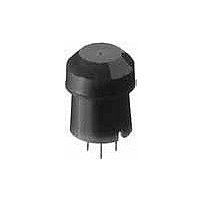
AMN12112
Manufacturer Part Number
AMN12112
Description
Industrial Motion & Position Sensors DIGITAL 5DC WHITE SLIGHT DETECTION
Manufacturer
Panasonic
Datasheet
1.AMN14112.pdf
(8 pages)
Specifications of AMN12112
Voltage Rating
3 VDC to 6 VDC
Temperature Range
- 20 C to + 60 C
Maximum Operating Temperature
+ 60 C
Maximum Voltage
6 VDC
Minimum Operating Temperature
- 20 C
Mounting Style
Through Hole
Product
Passive Infrared Sensors
Sensing Distance
20 cm
Supply Current
170 uA
Supply Voltage (max)
6 V
Supply Voltage (min)
3 V
Output Type
Digital
Lead Free Status / RoHS Status
Lead free / RoHS Compliant
Other names
PEWA
Available stocks
Company
Part Number
Manufacturer
Quantity
Price


MP Motion Sensor (AMN1,2,4)
HOW TO USE
1. Wiring diagram
1) Digital output
Vdd: Input power source (DC)
GND: GND
Out: Output (Comparator)
2. Timer circuit example
1) Digital output
3. Installation
Install the sensor so that people will be entering from the X or Y direc-
tion shown below. If persons approch the sensor from the Z direction,
detection distance will be shortened.
16
The transistor
turns on when
the sensor
detects
something
Note: This is the reference circuit which drives the MP motion sensor. Install a
Input voltage
Sensor
noise filter for applications requiring enhanced detection reliability and
noise withstanding capability.
Differences in the specifications of electronic components to which the
units are connected sometimes affect their correct operation; please
check the units' performance and reliability for each application.
GND
Relay
Select a transistor
to match the relay
10 µ
10 µ
47k
+
0.1 µ
+
13
Timer IC
3
5V
REG
74HC
123
10
11
2
9
8
0.1 µ
16
Iout: Max.100 µA
15
14
Vdd
GND
Out
1
47 µ
0.1 µ
R
C
+
Timer time = RXC
0.1 µ
10k
+
(5VDC)
0.1 µ
Load
Out
GND
Vdd
Connection
to motion
sensor
+
2) Analog output
2) Analog output
The transistor
turns on when
the sensor
detects
something
Note: This circuit is a sample of a drive circuit for the MP Motion Sensor. Its
Input voltage
Sensor
noise resistance and long-term reliability are not considered or investigat-
ed.
To improve the detection reliability and noise resistance of the circuit,
consider adding a noise filter.
Matsushita Electric Works, Ltd. accepts no responsibility for damages
resulting from the use of this circuit.
GND
Relay
OP
AMP
Select a
transistor
to match
the relay
10 µ
X direction ❍
10 µ
47k
Y direction ❍
+
0.1 µ
+
Timer IC
13
74HC
123
3
10
11
2
9
8
16
5V
REG
15
14
1
0.1 µ
0.1 µ
R
C
Vdd
GND
Out
X direction ❍
Timer time = RXC
47 µ
0.1 µ
10k
+
Window
comparator
Z direction ∆
(5VDC)
0.1 µ
Z
Microcomputer,
A/D converter
etc.
Vdd
Out
GND
Connection
to motion
sensor
Related parts for AMN12112
Image
Part Number
Description
Manufacturer
Datasheet
Request
R

Part Number:
Description:
Coin Cell Battery with Leads 3V 20mAH 2 PIN HORZ
Manufacturer:
Panasonic
Datasheet:
Part Number:
Description:
Coin Cell Battery with Leads 3V 48mAh 2 pin Vert
Manufacturer:
Panasonic
Part Number:
Description:
Coin Cell Battery 3V 12 X 2.5 mm 48mA
Manufacturer:
Panasonic
Datasheet:
Part Number:
Description:
Coin Cell Battery 3V 48mAh W/TABS
Manufacturer:
Panasonic
Datasheet:
Part Number:
Description:
Color CCD Linear Image Sensor with 1024 Pixels for R and B Colors/2048 Pixels for G Color
Manufacturer:
Panasonic
Datasheet:
Part Number:
Description:
2048-Bit CCD Linear Image Sensor
Manufacturer:
Panasonic
Datasheet:
Part Number:
Description:
2592-Bit CCD Linear Image Sensor
Manufacturer:
Panasonic
Datasheet:
Part Number:
Description:
2048-Bit High-Responsivity CCD Linear Image Sensor with Internal Clock Driver
Manufacturer:
Panasonic
Datasheet:
Part Number:
Description:
2880-Bit High-Responsivity CCD Linear Image Sensor
Manufacturer:
Panasonic
Datasheet:
Part Number:
Description:
Color CCD Linear Image Sensor with 512 Pixels for R and B Colors/1024 Pixels for G Color
Manufacturer:
Panasonic
Datasheet:
Part Number:
Description:
Quad analog switches
Manufacturer:
Panasonic
Datasheet:
Part Number:
Description:
ICs for TV
Manufacturer:
Panasonic
Datasheet:
Part Number:
Description:
IC for Liquid Crystal Color TV
Manufacturer:
Panasonic
Datasheet:
Part Number:
Description:
VCR cylinder direct motor drive circuit
Manufacturer:
Panasonic
Datasheet: