27929 Parallax Inc, 27929 Datasheet - Page 3
27929
Manufacturer Part Number
27929
Description
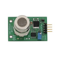
Flow Sensors CO2 Gas Sensor Module
Manufacturer
Parallax Inc
Datasheet
1.27929.pdf
(4 pages)
Specifications of 27929
Supply Voltage
6.5 V to 12 V
Lead Free Status / RoHS Status
Lead free / RoHS Compliant


Theory of Operation
The CO2 gas sensor module uses a gas sensor (MG811) from Hanwei Electronics. When the internal
heating element is activated, this gas sensor responds to CO2 gas by generating a small voltage in
proportion to the amount of CO2 gas present in the air exposed to the internal element. The sensor is a
high impedance device and requires a buffer/amplifier to measure the output. The output from the
buffer/amplifier (op-amp) is then sent to the inverting input of another op-amp in the same package
(LMC6035) which is configured as a comparator. A voltage divider formed by R3 is used to provide a
reference voltage. The output of this voltage divider is fed into the non-inverting inputs of the second
op-amp on the LMC6035 dual op-amp IC. The buffered output of the sensor can be measured for the
signal voltage at TP1 (+) and TP2 (-). The reference voltage is available at TP3 (+) and TP4 (-).
The output of op-amp B goes out to the ALR pin through a 1 kΩ resistor providing a TTL-compatible
signal to a microcontroller. This output also connects to a red LED on the gas sensor module. The trip
level adjustment is set via potentiometer R3. This is just a simple voltage divider that lets you set the
voltage from 0V to 3.3V. This voltage is compared to the voltage coming from the gas sensor buffer/op-
amp. When the voltage from the gas sensor is lower than the voltage set by potentiometer R3 the red
LED will light and the ALR output will be high (3.3 V). The voltage from the sensor actually drops as CO2
increases. The section below describes how to configure these gas sensor modules to detect gas with
minimal calibration.
Calibration
The procedure for setting the potentiometer is explained below.
potentiometer clockwise decreases voltage, while turning the potentiometer counter-clockwise increases
it. This can be compared to a water valve.
The gas sensor module’s ALR pin should only be checked when the heater is on and the readings have
stabilized.
Sources of Gas for Calibration / Testing
Your breath contains CO2 gas when you exhale. However you also have to be aware that contaminants
can affect the calibration of the sensor.
particulates. Breathing briefly on the sensor with a single breath is a convenient way to see it react to
CO2.
Resources and Downloads
You may download the manufacturer datasheet, etc. from the gas sensor product page on our website by
browsing to
Copyright © Parallax Inc.
Place the Gas Sensor Module in a clean air environment and supply power to the module. The
heater should be active during this time. Allow at least 5 minutes before making adjustments.
Measure the voltage at TP1 (+) and TP2 (-). It should be between 1.5 – 2V, but could be from
1V – 3.3V.
Adjust potentiometer R3 (Trip Level) until the voltage across TP3 (+) and TP4 (-) reads
approximately just below the reading from TP1/TP2. The LED should go out.
Apply your gas source to the gas sensor. The LED should light up.
Remove the gas source and allow the sensor to settle. The LED should go back out.
If the LED does not go out within 60 seconds, adjust R3 until the LED goes out and repeat the
two previous steps.
http://www.parallax.com
CO2 Gas Sensor Module (#27929)
and typing 27929 into our search box and clicking, “GO”.
Your breath also contains moisture and potentially other
Please note that turning the
v1.0 2/25/2010 Page 3 of 4
Related parts for 27929
Image
Part Number
Description
Manufacturer
Datasheet
Request
R


Part Number:
Description:
Microcontroller Modules & Accessories DISCONTINUED BY PARALLAX
Manufacturer:
Parallax Inc

Part Number:
Description:
BOOK UNDERSTANDING SIGNALS
Manufacturer:
Parallax Inc
Datasheet:


Part Number:
Description:
COMPETITION RING FOR SUMOBOT
Manufacturer:
Parallax Inc
Datasheet:


Part Number:
Description:
TEXT INFRARED REMOTE FOR BOE-BOT
Manufacturer:
Parallax Inc
Datasheet:
Part Number:
Description:
BOARD EXPERIMENT+LCD NX-1000
Manufacturer:
Parallax Inc
Datasheet:

Part Number:
Description:
CONTROLLER 16SERVO MOTOR CONTROL
Manufacturer:
Parallax Inc
Datasheet:

Part Number:
Description:
BASIC STAMP LOGIC ANALYZER
Manufacturer:
Parallax Inc
Datasheet:

Part Number:
Description:
IC MCU 2K FLASH 50MHZ SO-18
Manufacturer:
Parallax Inc
Datasheet: