E32-D32 Omron, E32-D32 Datasheet - Page 105
E32-D32
Manufacturer Part Number
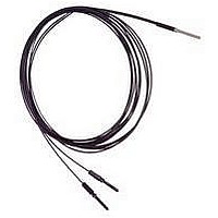
E32-D32
Description
Fiber Optic Sensors COAX DIFF CABLE
Manufacturer
Omron
Type
Fiber Optic Cablesr
Specifications of E32-D32
Cable Type
Fiber Optic Diffuse Top Beam
Features
Set-Mode blinking light source aids alignment
Sensing Method
Light
Sensing Distance
20.06 mm
Sensor Output
Analog
Sensor Housing
Barrel
Sensor Input
Fiber Optic
Sensing Range Max
100mm
Switch Terminals
Cable
Sensing Mode
Diffuse
Fiber Optic Sensor Type
General Purpose
Rohs Compliant
Yes
Lead Free Status / RoHS Status
Lead free / RoHS Compliant
Lead Free Status / RoHS Status
Lead free / RoHS Compliant, Lead free / RoHS Compliant
Available stocks
Company
Part Number
Manufacturer
Quantity
Price
Company:

Part Number:
E32-D32
Manufacturer:
OMRON
Quantity:
463


E32
Installation
J SENSING HEAD
Mounting Sensing Head in a Panel
Prepare a hole in the panel that can accommodate the threaded
cylindrical sensing head. Be sure to place the washer in front of
the mounting nut before inserting the sensing head through the
hole. Tighten the front mounting nut using no more than the
maximum torque recommended in the table.
Mounting Sensing Head in a Channel
Insert the sensing head at the desired location in the channel as
shown in the illustration, then use a set screw to fasten the head
in place. Apply no more than 2.6 in-lb of force in tightening the
set screw.
Tightening Torque
Use a proper-sized
wrench and do not
exceed the torque
recommended for the
sensing head.
Sensing heads
M3 and M4 threads
M6 threads
2 mm dia., no thread
3 mm dia., no thread
E32-D14L
E32-T12F
E32-D12F
E32-T16
E32-R21
E32-M21
E32-L25A
Nuts
(attachment)
Retaining screw
(M 3 max.)
Spring mounting clip
Toothed washers
Maximum torque
6.88 in-lb
8.66 in-lb
2.6 in-lb
2.6 in-lb
8.66 in-lb
6.88 in-lb
6.88 in-lb
4.33 in-lb
5.2 in-lb
4.33 in-lb
6.88 in-lb
106
J CUTTING FIBER
Insert a fiber into the Fiber and determine the length of the fiber
to be cut.
Press down the Fiber Cutter in a single stroke to cut the fiber.
When the fiber is cut, an insertion mark is inscribed on the fiber.
Insert a fiber into the Fiber Cutter in the direction indicated by the
arrow (refer to the following figure).
The cutting holes cannot be used twice. If the same hole is used
twice, the cutting face of the fiber will be rough and the sensing
distance will be reduced. Always use an unused hole.
Use either one of the two holes on the right (refer to the following
figure) to cut a thin fiber as follows:
1. An attachment is temporarily fitted to a thin fiber before
2. Secure the attachment after adjusting the position of it in the
3. Insert the fiber into the E39-F4 to cut.
Note: Insert the fiber in the direction indicated by the arrow.
Three holes for
standard fiber
(2.2 mm dia.)
For a 2.2-mm dia. standard fiber only.
2
shipment.
direction indicated by the arrow.
12.6
2.2-dia.
Insertion mark
1
Temporarily fitted
Cutter E39-F4
Two holes for
thin fiber
E32
Related parts for E32-D32
Image
Part Number
Description
Manufacturer
Datasheet
Request
R

Part Number:
Description:
Fiber Optic Sensors 1.5mm DIA FLEXIBLE D IFFUSE FO
Manufacturer:
Omron
Datasheet:
Part Number:
Description:
Fiber Optic Sensors HIGHFLEX HIGHTEMP D IFFUSE R10
Manufacturer:
Omron
Datasheet:
Part Number:
Description:
E32-R21 Retroreflective Type Fiber-Optic Cable, M6 Screw Head Retroflective Beam Fiber Cable Suitable For Transparent Object Detection
Manufacturer:
Omron
Datasheet:
Part Number:
Description:
SEP, STRAT, 3.5CM SD
Manufacturer:
Omron
Datasheet:

Part Number:
Description:
5 METER CABLE LENGTH
Manufacturer:
Omron
Datasheet:
Part Number:
Description:
TB,Narrow Vision Field 3.0 Deg
Manufacturer:
Omron
Datasheet:

Part Number:
Description:
G6S-2GLow Signal Relay
Manufacturer:
Omron Corporation
Datasheet:
Part Number:
Description:
Compact, Low-cost, SSR Switching 5 to 20 A
Manufacturer:
Omron Corporation
Datasheet:
Part Number:
Description:
Manufacturer:
Omron Corporation
Datasheet: