E32-D32 Omron, E32-D32 Datasheet - Page 56
E32-D32
Manufacturer Part Number
E32-D32
Description
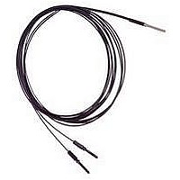
Fiber Optic Sensors COAX DIFF CABLE
Manufacturer
Omron
Type
Fiber Optic Cablesr
Specifications of E32-D32
Cable Type
Fiber Optic Diffuse Top Beam
Features
Set-Mode blinking light source aids alignment
Sensing Method
Light
Sensing Distance
20.06 mm
Sensor Output
Analog
Sensor Housing
Barrel
Sensor Input
Fiber Optic
Sensing Range Max
100mm
Switch Terminals
Cable
Sensing Mode
Diffuse
Fiber Optic Sensor Type
General Purpose
Rohs Compliant
Yes
Lead Free Status / RoHS Status
Lead free / RoHS Compliant
Lead Free Status / RoHS Status
Lead free / RoHS Compliant, Lead free / RoHS Compliant
Available stocks
Company
Part Number
Manufacturer
Quantity
Price
Company:

Part Number:
E32-D32
Manufacturer:
OMRON
Quantity:
463


E32-D51
E32-D81R-S
E32-D81R
E32-D61-S
E32-D61
E32-D73-S
E32-D73
E32-D12F
56
Fiber Units with Reflective Sensors
Environment-resistant Models
Environment-resistant Models
3.1
Note: The maximum allowable temperature is 150°C. The maximum
Sensing surface
1 dia.
Sensing surface
1.2 dia.
M4×0.7
Sensing surface
Two, 1.5 dia.
16
16
Sensing surface 1.4 dia.
6 dia.
6 dia. (Fluororesin)
R35
allowable temperature for continuous operation is 130°C.
R25
3
R25
4.9
R40
R10
3
5
R25
R25
R10
2
20
20
2
20
20
3
Stainless-steel tube
1.25 dia.
1.65 dia.
60
60
M6×0.75
M6×0.75 (SUS303)
Width 10, thickness 2.4 (SUS303)
Washer (SUS)
17
17
13
M4×0.7
Width 10, thickness 2.4 (SUS303)
Washer (SUS)
M6×0.75
M6×0.75 (SUS303)
5 *3
5
5 dia. *2
M6×0.75
M6×0.75 (brass/nickel plating)
(70)
A
A
Protective tube
5
2,000
Width 10, thickness 2.4 (nickel-plated brass)
Washer (nickel-plated iron)
A
2.5 dia.
2,000
2,000
SUS flexible tube 3.5 dia.
20
20
Using the E32-D81R-S
Using the E32-D61-S
Using the E32-D73-S
M4×0.7
M4×0.7 (SUS303)
Width 7, thickness 2.4 (SUS304)
Washer (SUS)
10
Fluororesin tube
4 dia.
Chemical-resistant Models
Heat-resistant Models
5 dia.
2,000
2,000
B
25(B)
25(B)
SUS flexible tube 2.8 dia.
2.2 dia.
*
*1
2.2 dia.
25(C)
5
5
2.2 dia.
*
Two, 2.2 dia.
Two 2.2 dia.
4.5
*2. The diameter is 6 dia. if the fiber length exceeds 10 m.
*3. The diameter is 10 if the fiber length exceeds 10 m.
4.5
100
8.5
8.5
5
4.5
8.5
E32-D14F
Using the E32-D73
Using the E32-D81R
Using the E32-D61
Hexagonal caulking
Flexible
29. 5(B)
Hexagonal caulking
29.5(B)
29.5(C)
4.5
SUS316L
Cutting free (Cutter provided)
SUS303
SUS316L
2.2 dia.
R40
Optical axis confirmation mark (red)
*
*1
*
26
26
Break-resistant
7 dia.
7 dia. (fluororesin)
6.4
6.4
6.4
8 15
Note 1. The maximum allowable temperatures
8
8
Note 1. The maximum allowable temperatures
15
Note 1. The maximum allowable tempera-
15
2,000
2. Order the Fiber Unit based on the Amplifier
2. Order the Fiber Unit based on the Amplifier
Unit. Use the E32-D61-S if the E3X-DA@-S,
E3X-MDA@, or E3X-DAC@-S is used. Use
the E32-D61 if any other Amplifier is used.
2. Order the Fiber Unit based on the
for sections A and B are 350°C and
110°C, respectively. The section insert-
ed into the Amplifier Unit (indicated by
*1), however, must stay within the Ampli-
fier Unit's operating temperature range.
Unit. Use the E32-D81R-S if the E3X-
DA@-S, E3X-MDA@, or E3X-DAC@-S is
used. Use the E32-D81R if any other
Amplifier is used.
for sections A and B are 200°C and
110°C, respectively. The section in-
serted into the Amplifier Unit (indicated
by *), however, must stay within the
Amplifier Unit's operating temperature
range.
Fluororesin coating
Amplifier Unit. Use the E32-D@-S if the
E3X-DA@-S, E3X-MDA@, or
E3XDAC@-S is used. Use the E32-D@ if
any other Amplifier is used.
tures for sections A, B, and C are
400°C, 300°C, and 110°C, respec-
tively. The section inserted into the
Amplifier Unit (indicated by *), how-
ever, must stay within the Amplifier
Unit's operating temperature range.
Two, 2.2 dia.
R@
100
Standard
Related parts for E32-D32
Image
Part Number
Description
Manufacturer
Datasheet
Request
R

Part Number:
Description:
Fiber Optic Sensors 1.5mm DIA FLEXIBLE D IFFUSE FO
Manufacturer:
Omron
Datasheet:
Part Number:
Description:
Fiber Optic Sensors HIGHFLEX HIGHTEMP D IFFUSE R10
Manufacturer:
Omron
Datasheet:
Part Number:
Description:
E32-R21 Retroreflective Type Fiber-Optic Cable, M6 Screw Head Retroflective Beam Fiber Cable Suitable For Transparent Object Detection
Manufacturer:
Omron
Datasheet:
Part Number:
Description:
SEP, STRAT, 3.5CM SD
Manufacturer:
Omron
Datasheet:

Part Number:
Description:
5 METER CABLE LENGTH
Manufacturer:
Omron
Datasheet:
Part Number:
Description:
TB,Narrow Vision Field 3.0 Deg
Manufacturer:
Omron
Datasheet:

Part Number:
Description:
G6S-2GLow Signal Relay
Manufacturer:
Omron Corporation
Datasheet:
Part Number:
Description:
Compact, Low-cost, SSR Switching 5 to 20 A
Manufacturer:
Omron Corporation
Datasheet:
Part Number:
Description:
Manufacturer:
Omron Corporation
Datasheet: