E32-D24 Omron, E32-D24 Datasheet - Page 107
E32-D24
Manufacturer Part Number
E32-D24
Description
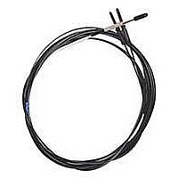
Fiber Optic Sensors SIDE VIEW CABLE
Manufacturer
Omron
Type
Fiber Optic Cablesr
Specifications of E32-D24
Cable Type
Fiber Optic Diffuse Side Beam
Features
Set-Mode blinking light source aids alignment
Sensing Method
Light
Sensing Distance
15.24 mm
Sensor Output
Analog
Sensor Housing
Barrel
Sensor Input
Fiber Optic
Sensing Range Max
40mm
Switch Terminals
Cable
Sensing Mode
Diffuse
Fiber Optic Sensor Type
Side Sensing
Rohs Compliant
Yes
Lead Free Status / RoHS Status
Lead free / RoHS Compliant
Lead Free Status / RoHS Status
Lead free / RoHS Compliant, Lead free / RoHS Compliant


E32
J INSTALLING FIBER CABLES
Bends in Fiber cables
Plastic and glass filament fiber cables may be bent to avoid
obstacles on the way to the sensing site. Here are some
guidelines about the location of cable bends: The first bend must
be as least 20 mm (0.79 in) away from where the cables enter
the amplifier. The last bend must be at least 20 mm (0.79 in)
bending the sensing head. We recommend a 25 mm (1.0 in)
minimum radius for a right angle bend to maintain the rated
sensing distance. The sharpest allowable right angle bend is over
a 10 mm (0.39 in) radius, but this will result in a shorter sensing
distance. Refer to the bending radius graph.
Do not apply excess force on the Fiber Units.
Do not pull or press the Fiber Units. The Fiber Units have a
withstand force of 1 kg or 3 kg (pay utmost attention because the
fibers are thin).
Do not bend the Fiber Units beyond the permissible bending
radius.
Do not bend the edge of the Fiber Units.
Correct
Incorrect
(0.197) (0.394) (0.591) (0.787) (0.984) (1.181)
Bending radius [mm (inch)]
Bending
radius
Amplifier
40 mm max.
E3S1- - X3 amplifier with
E32-DC200 diffuse
reflective fiber cable
20 mm max.
Fiber unit
108
Proper Supports for Cables
To support the fiber cable between the sensing site and the
amplifier, mount the cable using a nylon strap or cable tie. Do not
use a U-shaped strap that will compress or put stress on the fiber
cable. To prevent damage from excessive vibration, take up the
fiber in a loop as shown below.
The Fiber Head could be broken by excessive vibration. To
prevent this, the following is effective:
J LONGER FIBER-OPTIC CABLES
Applicable Models
E32-TC200/-DC200
E32-TC200B/-DC200B
E32-TC200E/-DC200E
E32-TC200F/-DC200F
E32-TC200A
Appearance
E39-F10 Fiber Connector
Use the following procedure (refer to the figure) to connect fibers
via the Fiber Connector.
Each fiber should be as close as possible before they are
connected.
Sensing distance will be reduced by approximately 25% when
fibers are connected.
Only fibers with 2.2 mm dia. can be connected.
Correct
Incorrect
Retention Unit
The length can be ordered in increments of 1 m between
6 m min. and 20 m max. (2-m and 5-m fiber length types are
standard for E32-TC200, E32-DC200.)
A one-turn loop can
absorb vibrations.
Splice
Fiber unit
Nylon wireholder
Tape
Retention Unit
ℓ
Metal holder
E32
Related parts for E32-D24
Image
Part Number
Description
Manufacturer
Datasheet
Request
R

Part Number:
Description:
Fiber Optic Sensors 1.5mm DIA FLEXIBLE D IFFUSE FO
Manufacturer:
Omron
Datasheet:
Part Number:
Description:
Fiber Optic Sensors HIGHFLEX HIGHTEMP D IFFUSE R10
Manufacturer:
Omron
Datasheet:
Part Number:
Description:
E32-R21 Retroreflective Type Fiber-Optic Cable, M6 Screw Head Retroflective Beam Fiber Cable Suitable For Transparent Object Detection
Manufacturer:
Omron
Datasheet:
Part Number:
Description:
SEP, STRAT, 3.5CM SD
Manufacturer:
Omron
Datasheet:

Part Number:
Description:
5 METER CABLE LENGTH
Manufacturer:
Omron
Datasheet:
Part Number:
Description:
TB,Narrow Vision Field 3.0 Deg
Manufacturer:
Omron
Datasheet:

Part Number:
Description:
G6S-2GLow Signal Relay
Manufacturer:
Omron Corporation
Datasheet:
Part Number:
Description:
Compact, Low-cost, SSR Switching 5 to 20 A
Manufacturer:
Omron Corporation
Datasheet:
Part Number:
Description:
Manufacturer:
Omron Corporation
Datasheet: