D4B-1116N Omron, D4B-1116N Datasheet - Page 6
D4B-1116N
Manufacturer Part Number
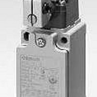
D4B-1116N
Description
Basic / Snap Action / Limit Switches Adjustable Lever PG13.5 1NC/1NO
Manufacturer
Omron
Specifications of D4B-1116N
Contact Form
NO / NC
Contact Rating
2 Amps
Actuator
Lever, Roller
Operating Force
9.41 N
Termination Style
Screw
Actuation Type
Adjustable Roller Lever
Operating Force Max
960gf
Switch Operation
Snap Action
Contact Voltage Ac Max
600V
Contact Current Ac Max
10A
Switch Terminals
Screw
Svhc
No SVHC (15-Dec-2010)
Lead Free Status / RoHS Status
Lead free / RoHS Compliant
Lead Free Status / RoHS Status
Lead free / RoHS Compliant


Ratings
Note: 1. The above values are continuous currents.
Characteristics
Note: 1. The above values are initial values.
*1. The degree of protection is tested using the method specified by the standard (EN60947-5-1). Confirm that sealing properties are sufficient for
*2. The durability is for an ambient temperature of 5 to 35°C and ambient humidity of 40% to 70%. For further conditions, consult your OMRON
*3. –20 to 80°C for the flexible-rod type.
*4. The above values may vary depending on switching frequency, environmental condition, and relativity level, consult your OMRON sales
125 VAC
250
400
8 VDC
14
30
125
250
Inrush current
Degree of protection *1
Durability *2
Operating speed
Operating frequency
Contact resistance
Minimum applicable load *4
Rated insulation voltage (U
Rated frequency
Protection against electric shock
Pollution degree (operating environment)
Impulse withstand voltage
(EN60947-5-1)
Insulation resistance
Contact gap
Vibration resistance
Shock resistance
Conditional short-circuit current
Conventional enclosed thermal current (I
Ambient operating temperature
Ambient operating humidity
Weight
Rated voltage (V)
the operating conditions and environment beforehand.
sales representative.
representative.
2. Inductive loads have a power factor of 0.4 or higher (AC) or a time constant of 7 ms or lower (DC).
3. Lamp loads have a inrush current of 10 times the normal current.
4. Motor loads have a inrush current of 6 times the normal current.
2. The above values may vary depending on the model. Consult your OMRON sales representative for details.
30 A max.
10
10
10
10
10
6
0.8
0.4
NC
i
Resistive load
)
Mechanical
Electrical
Mechanical
Electrical
Between terminals
of same polarity
Between terminals
of different polarity
Between each
terminal and ground
Malfunction
Destruction
Malfunction
Non-inductive load (A)
NO
the
)
IP67 (EN60947-5-1)
30,000,000 operations min. (snap-action)
10,000,000 operations min. (slow-action)
500,000 operations min. (10 A resistive load at 250 VAC)
1 mm/s to 0.5 m/s
120 operations/minute
30 operations/minute
25 mΩ max.
General load
Gold-clad contact 20 mA resistive load at 5 VAC
(N-level reference value)
600 V (EN60947-5-1)
50/60 Hz
Class I (with ground terminal)
3 (EN60947-5-1)
2.5 kV (snap-action)/4 kV (slow-action)
4 kV (slow-action)
4 kV
100 MΩ min. (at 500 VDC) between terminals of the same polarity and between each
terminal and non-current-carrying part
2 × 2 mm min. (slow-action)
2 × 0.5 mm min. (snap-action)
10 to 55 Hz, 0.75 mm single amplitude
1,000 m/s
300 m/s
100 A (EN60947-5-1)
20 A (EN60947-5-1)
–40 to 80°C (with no icing) *3
95% max.
Approx. 250 g
3
2
1.5
6
6
4
0.2
0.1
NC
2
Lamp load
min.
2
min.
1.5
1
0.8
3
3
3
0.2
0.1
180 mA resistive load at 5 VAC
NO
10
10
10
10
3
6
0.8
0.4
NC
Inductive load
Inductive load (A)
NO
5
3
1.5
6
6
4
0.2
0.1
NC
Motor load
D4B-@N
2.5
1.5
0.8
NO
6
Related parts for D4B-1116N
Image
Part Number
Description
Manufacturer
Datasheet
Request
R

Part Number:
Description:
LSW,PG13.5,SNAP,TOP PLNGR
Manufacturer:
Omron
Datasheet:

Part Number:
Description:
Safety Limit Switch
Manufacturer:
Omron
Datasheet:

Part Number:
Description:
SWITCHES
Manufacturer:
Omron
Datasheet:

Part Number:
Description:
LIMIT SWITCH ADJ ROLL LEVER
Manufacturer:
Omron
Datasheet:

Part Number:
Description:
G6S-2GLow Signal Relay
Manufacturer:
Omron Corporation
Datasheet:
Part Number:
Description:
Compact, Low-cost, SSR Switching 5 to 20 A
Manufacturer:
Omron Corporation
Datasheet:
Part Number:
Description:
Manufacturer:
Omron Corporation
Datasheet: