821TD10H-UNI Magnecraft / Schneider Electric, 821TD10H-UNI Datasheet

Time Delay & Timing Relays 12-240VAC/VDC 17.5MM

821TD10H-UNI

Manufacturer Part Number
821TD10H-UNI
Description
Time Delay & Timing Relays 12-240VAC/VDC 17.5MM
Manufacturer
Magnecraft / Schneider Electric
Datasheet

Specifications of 821TD10H-UNI

Contact Form
SPDT
Contact Rating
15 A
Contact Configuration
SPDT
Nom Input Voltage
240V
Delay Time Range
0.1s To 10day
Relay Mounting
DIN Rail
Contact Current Ac Max
15A
Height
88.9mm
Mounting Type
DIN Rail
Brand/series
820 Series
Current, Rating
15 A
Display Type
LED
Function
Timing
Material, Contact
Silver-Nickel 90⁄10
Relay Type
Electro Mechanical
Standards
UL, CE, RoHS
Temperature, Operating, Maximum
55 °C
Temperature, Operating, Minimum
-20 °C
Timer Type
Single Shot
Timing Range
0.1 sec. to 10 Days
Voltage, Control
240 VAC⁄VDC
Voltage, Rating
240⁄24 VAC⁄VDC
Ten Time Scales
0.1 Seconds to 10 days
Timing Adjustment
Screwdriver Slot
Rohs Compliant
Yes
Accuracy
0.2 %
Lead Free Status / RoHS Status
Lead free / RoHS Compliant
Lead Free Status / RoHS Status
Lead free / RoHS Compliant, Lead free / RoHS Compliant
Time Delay Relays – Application Data
Definition:
Time Delay is defined as the controlled period between the functioning of two events. A Time Delay relay is a combination
of an electromechanical output relay and a control circuit. The control circuit is comprised of solid state components and
timing circuits that control operation of the relay and timing range. Typical time delay functions include On-Delay, Repeat
cycle (starting off), Interval, Off-Delay, Retriggerable One Shot, Repeat cycle (starting on), Pulse Generator, One Shot,
On/Off Delay, and Memory Latch. Each function is explained in the table below. Time delay relays have a broad
choice of timing ranges from less than one second to many days. There are many choices of timing adjustments from
calibrated external knobs, DIP switches, thumbwheel switches, or recessed potentiometer. The output contacts on the
electromechanical output relay are direct wired to the output terminals. The contact load ratings are specified for each
specific type of time delay relay.
Understanding the differences between all the functions available in time delay relays can sometimes be a daunting task.
When designing circuits using time delay relays questions such as:
“What initiates a time delay relay?”
“Does the timing start with the application or release of voltage?”
“When does the output relay come on?”
must be asked.
Time delay relays are simply control relays with a time delay built in. Their purpose is to control an event based on time.
The difference between relays and time delay relays is when the output contacts open & close: on a control relay, it
happens when voltage is applied and removed from the coil; on time delay relays, the contacts will open or close before
or after a pre-selected, timed interval.
Typically, time delay relays are initiated or triggered by one of two methods:
• application of input voltage (On Delay, Interval On, Flasher, Repeat Cycle, Delayed Interval & Interval/Flasher).
• opening or closing of a trigger signal (Off Delay, Single Shot & Watchdog).
These trigger signals can be one of two designs:
• a control switch (dry contact), i.e., limit switch, push button, float switch, etc.
• voltage (commonly known as a power trigger).
To help understand, some definitions are important:
Input Voltage: Control voltage applied to the input terminals (see wiring diagrams below). Depending on the function,
input voltage will either initiate the unit or make it ready to initiate when a trigger signal is applied.
Trigger Signal: On certain timing functions, a trigger signal is used to initiate the unit after input voltage has been applied.
As noted above, this trigger signal can either be a control switch (dry contact switch) or a power trigger (voltage).
Output (Load): Every time delay relay has an internal relay (usually mechanical) with contacts that open & close to control
the load. They are represented by the dotted lines in the wiring diagrams. Note that the user must provide the voltage to
power the load being switched by the output contacts of the time delay relay.
The following tables contain both written and visual descriptions on how the common timing functions operate. A Timing
Chart shows the relationship between Input Voltage, Trigger Signal (if present) and Output Contacts.
5/2
M agne cr aft S olu tion Guide 1 0 5 A

Related parts for 821TD10H-UNI

821TD10H-UNI Summary of contents

Page 1

... Time delay relays are simply control relays with a time delay built in. Their purpose is to control an event based on time. The difference between relays and time delay relays is when the output contacts open & close control relay, it happens when voltage is applied and removed from the coil ...

Page 2

... REPEAT CYCLE and time delay t begins. When time delay t is complete, contacts return to Starting On their shelf state for time delay t. This cycle will repeat until input voltage U is removed. Trigger switch is not used in this function. G. Upon application of input voltage U, a single output pulse of 0.5 seconds is PULSE delivered to relay after time delay t ...

Page 3

... Advantages of the 820 Series Time Delay Relays Input Indication Green LED Light. Input Terminals Accepts AWG Wire. 5/4 Output Indication Red LED Light. Time Setting Select Between 10 Different Time Scales. DIN Rail Mounting Mounts Directly On a DIN Rail. Fine Time Setting Ultimate Control in Accuracy ...

Page 4

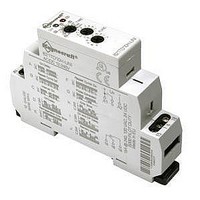
... The new 820 Series Time Delay Relays are DIN rail mountable products offering 10 different timing functions, 2 status LEDs, ultra-wide timing range (0.1 sec to 10 days) and a universal voltage input (12-240 VAC/VDC) all in one modular package. The 821 is available amp SPDT timer while its counterpart 822 is available as a DPDT timer also capable of switching amps per pole ...

Page 5

... V AWG (mm2 (Nm) °C °C grams Time Setting Fine Time Setting Function Output Terminals DPDT (822 Version Only) Output Terminals DIN Mount 821TD10H-UNI 822TD10H-UNI SPDT Silver Alloy 15 240 AC, 50/60 Hz 240 AC, 50/ 1/2 @ 120VAC 1/2 @ 120VAC 1 @ 240 VAC 1 @ 240 VAC B300 100 Red 12… ...

Page 6

... See Section 3 p.18 Rated Load Current SPDT 15 Amps DPDT 15 Amps – Input Voltage UNI = 12...240 VAC/VDC 0.6 (14.2) INPUT VOLTAGE VOLTAGE EXTERNAL CONTROL 0.7 SWITCH (16.71 INPUT VOLTAGE 821TD10H-UNI 822TD10H-UNI COMMON 16 - NORMALLY CLOSED NORMALLY OPEN COMMON 26 - NORMALLY CLOSED NORMALLY OPEN 822TD10H-UNI INPUT 5/7 ...

Related keywords