GRF103-12 TELEDYNE, GRF103-12 Datasheet

RF (Radio Frequency) Relays 12V DC-6GHz .10W hi sensitivity

GRF103-12

Manufacturer Part Number
GRF103-12
Description
RF (Radio Frequency) Relays 12V DC-6GHz .10W hi sensitivity
Manufacturer
TELEDYNE
Series
GRF103r
Datasheet

Specifications of GRF103-12

Coil Current
0.10 W
Frequency
6 GHz
Contact Form
DPDT
Coil Voltage
12 VDC
Power Consumption
180 mW
Termination Style
PCB
Lead Free Status / RoHS Status
Lead free / RoHS Compliant
©2003 TELEDYNE RELAYS
Temperature
(Ambient)
Vibration
(General Note 1)
Shock
(General Note 1)
Enclosure
Weight
INTERNAL CONSTRUCTION
PHYSICAL SPECIFICATIONS
ENVIRONMENTAL AND
Storage
Operating –55°C to +85°C
GRF100
GRF103
DESIGNATION
GRF100
GRF103
SERIES
–65°C to +125°C
10 g’s to 500 Hz
30 g’s,
6 msec, half-sine
Hermetically sealed
0.09 oz. (2.55g) max.
0.16 oz. (4.5g) max.
SPECIFICATIONS ARE SUBJECT TO CHANGE WITHOUT NOTICE
Repeatable, RF Centigrid
Sensitive, repeatable, RF Centigrid
HIGH REPEATABILITY,
CENTIGRID
SURFACE MOUNT,
DESCRIPTION
The ultraminiature GRF100 and GRF103 relays are designed to provide a
practical surface-mount solution with improved RF signal repeatability over the
frequency range. GRF100 and GRF103 relays feature a unique ground shield
that isolates and shields each lead to ensure excellent contact-to-contact and
pole-to-pole isolation. This ground shield provides a ground interface that
results in improved high-frequency performance as well as parametric
repeatability. The GRF100 and GRF103 extend performance advantages over
similar RF devices that simply offer formed leads for surface mounting.
These relays are engineered for use in RF attenuator, RF switch matrices, ATE
and other applications that require dependable high frequency signal fidelity
and performance.
The GRF100 and GRF103 feature:
• High repeatability
• Broader bandwidth
• Metal enclosure for EMI shielding
• High isolation between control and signal paths
• High resistance to ESD
The following unique construction features and manufacturing techniques
provide excellent robustness to environmental extremes and overall high
reliability:
• Uniframe motor design provides high magnetic efficiency and mechanical
• Minimum mass components and welded construction provide maximum
• Advanced cleaning techniques provide maximum assurance of internal
• Gold-plated precious metal alloy contacts ensure reliable switching
• Hermetically sealed
rigidity
resistance to shock and vibration
cleanliness
BROADBAND
www.teledynerelays.com
DPDT
®
relay
®
RELAY TYPE
RELAYS
®
relay
GRF100 GRF103 Page 1
GRF100
GRF103
SERIES
GRF100 GRF103/1203/Q1

Related parts for GRF103-12

GRF103-12 Summary of contents

Page 1

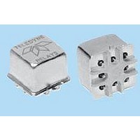
... The ultraminiature GRF100 and GRF103 relays are designed to provide a practical surface-mount solution with improved RF signal repeatability over the frequency range. GRF100 and GRF103 relays feature a unique ground shield that isolates and shields each lead to ensure excellent contact-to-contact and pole-to-pole isolation. This ground shield provides a ground interface that results in improved high-frequency performance as well as parametric repeatability ...

Page 2

... SERIES GRF100 AND GRF103 TYPICAL RF CHARACTERISTICS (See RF Notes) Isolation Across Contacts (RF Note 4) -20 -30 -40 -50 -60 0 500 1000 1500 2000 2500 3000 3500 Frequency (MHz) Insertion Loss (RF Note 6) 0 -0.2 -0.4 -0.6 -0.8 -1 -1.2 -1.4 -1.6 -1.8 0 500 1000 1500 2000 2500 ...

Page 3

... SMA connectors. (RT/duroid www.teledynerelays.com Normally Open 0.06 0.08 0.1 0.12 0.14 0.16 0.18 0.2 Repeatability (dB) Normally Open 0.06 0.08 0.1 0.12 0.14 0.16 0.18 0.2 Repeatability (dB) ® GRF100 GRF103 Page 3 GRF100 GRF103/1203/Q1 ...

Page 4

... Butt-lead ends are coplanar within .003" (0.08). 5. Application notes available for PCB layout and mounting information. GRF100 GRF103 Page 4 SPECIFICATIONS ARE SUBJECT TO CHANGE WITHOUT NOTICE GRF100-12: 369 mW typical @ nominal rated voltage GRF103-12: 180 mW typical @ nominal rated voltage GRF100-5 GRF103-5 5.0 GRF100 50 GRF103 100 3 ...

Page 5

... Dimensions are in inches (mm). 4. Unless otherwise speci¿ ed, tolerance is ± .010 (.25). 5. Add the contact resistance show in the datasheet. 6. Add 0.01 oz. (0. the weight of the relay assembly shown in the datasheet. © 2008 Teledyne Relays Appendix A: Spacer Pads Height For use with the following: ...

Page 6

... Dim H MAX .014 [0.36] (REF) .370 [9.4] MIN +44 (0) 1236 453124 • www.teledyne-europe.com For use with the following: ER411T, J411T, ER412, ER412D ER412DD, J412, J412D, J412DD ER412T, J412T 712, 712D, 712TN ER431T, J431T, ER432, ER432D ER432DD, J432, J432D, J432DD ER432T, J432T ...

Page 7

... Centigrid® Relays: RF180, ER116C, 122C, ER136C Indicates ground pin position Indicates glass insulated lead position Indicates ground pin or lead position depending on relay type © 2008 Teledyne Relays "Z" POSITION "X" POSITION "Y" POSITION TO-5 Relays: ER411, ER431, RF311, RF331 " ...

Related keywords