GRF180-5 TELEDYNE, GRF180-5 Datasheet
GRF180-5
Manufacturer Part Number
GRF180-5
Description
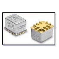
RF (Radio Frequency) Relays 5V DC-6GHz .15W
Manufacturer
TELEDYNE
Series
GRF180r
Specifications of GRF180-5
Coil Current
0.15 W
Frequency
6 GHz
Contact Form
2 Form C (DPDT)
Coil Voltage
5 VDC
Power Consumption
410 mW
Termination Style
PCB
Brand/series
GRF180 Series
Current, Rating
0.25 A
Function
Latching
Latch Type
Magnetic
Mounting Type
PCB
Number Of Pins
10
Relay Type
Electro Mechanical
Termination
Surface Mount
Voltage, Control
5 VDC
Voltage, Rating
28 VDC
Lead Free Status / RoHS Status
Lead free / RoHS Compliant


©2003 TELEDYNE RELAYS
DESCRIPTION
The Series GRF180 relay is the first hermetically sealed,
ultraminiature RF relay designed from inception for surface
mount applications. This magnetic-latching relay features
extremely low internal circuit losses for exceptional time and
frequency domain response characteristics through and
beyond the UHF spectrum and into the S band. The GRF180
features a unique ground shield that isolates and shields
each lead to ensure excellent contact-to-contact and pole-to-
pole isolation. This ground shield provides a ground interface
that results in improved high-frequency performance as well
as
performance advantages over similar RF devices that simply
offer formed leads for surface mounting.
The GRF180 is robust to shock, vibration and temperature
extremes for use in space applications and other demanding
environments. It is engineered for use in RF attenuators, RF
PRINCIPLE OF OPERATION
Energizing Coil A produces a
magnetic field opposing the
magnetic
permanent magnet in Circuit
A. As the net holding force
decreases,
force in the air gap of Circuit
B, which also results from the
magnetic
permanent magnet, becomes
great enough to break the
armature free of Core A, and
snap it into a closed position against Core B. The armature remains in this
position upon removal of power from Coil A, but will snap back into position
A upon energizing Coil B. Since operation depends upon cancellation of a
magnetic field, it is necessary to apply the correct polarity to the relay coils
as indicated on the relay schematic.
When latching relays are installed in equipment, the latch and reset coils
should not be pulsed simultaneously. Coils should not be pulsed with less
than rated coil voltage and the pulse width should be a minimum of three
times the specified operate time of the relay. If these conditions are not
followed, it is possible for the relay to be in the magnetic neutral position.
parametric
field
field
the
repeatability. The
attractive
of
of
the
the
MAGNETIC CIRCUIT B
SPECIFICATIONS ARE SUBJECT TO CHANGE WITHOUT NOTICE
AIR GAP
COIL B
PERMANENT MAGNET
GRF180
MAGNETIC-LATCHING
ARMATURE
SURFACE MOUNT,
BROADBAND
extends
RF RELAYS
MAGNETIC CIRCUIT A
SOFT IRON CORE A
SOFT IRON FRAME
DPDT
COIL A
MOVING
CONTACT
switch matrices, automated test equipment, spacecraft and
other applications that require dependable high-frequency
signal fidelity and performance. Its low profile and .100" grid
spaced terminals make the GRF180 ideal for applications
where extreme packaging density and/or close PC board
spacing are required.
Unique features and manufacturing techniques include:
• Positive mounting means to RF ground plane.
• Unique uniframe design provides high magnetic efficiency
• High force/mass ratios for resistance to shock and
• Advanced
• Gold-plated precious metal alloy contacts ensure reliable dc
• Robust to high temperature solder reflow environments.
and mechanical rigidity.
vibration.
assurance of internal cleanliness.
and RF signal switching, as well as low and stable insertion
loss.
STATIONARY
CONTACT
cleaning
Temperature
(Ambient)
Vibration
(General Note 1)
Shock
(General Note 1)
Enclosure
Weight
PHYSICAL SPECIFICATIONS
techniques
ENVIRONMENTAL AND
Storage
Operating –55°C to +85°C
GRF180
provide
SERIES
–65°C to +125°C
30 g’s to 500 Hz
100 g’s,
6 msec, half-sine
Hermetically sealed
0.10 oz. (2.9g) max.
GRF180 Page 12
maximum
GRF180/1203/Q1
Related parts for GRF180-5
Image
Part Number
Description
Manufacturer
Datasheet
Request
R

Part Number:
Description:
RF (Radio Frequency) Relays 12V DC-6GHz .15W
Manufacturer:
TELEDYNE
Datasheet:

Part Number:
Description:
Relay; E-Mech; Freq (RF); DPDT; Cur-Rtg 1A; Ctrl-V 5DC; Vol-Rtg 28DC; PCB Mnt; 10 Pin
Manufacturer:
TELEDYNE
Datasheet:
Part Number:
Description:
Module; Thru Hole; Solid-State; 3.5 mA @ 115 V (RMS), 3.0 mA @ 220 V (RMS); 7
Manufacturer:
TELEDYNE
Datasheet:
Part Number:
Description:
Module; Thru Hole; Solid-State; 15 mA (Max.); 3.8 to 16 V (RMS); 3 VDC (Min.)
Manufacturer:
TELEDYNE
Datasheet:
Part Number:
Description:
Relay; Hybrid; Freq (RF); DPDT; Cur-Rtg 1A; Ctrl-V 12DC; Vol-Rtg 28DC; PCB Mnt
Manufacturer:
TELEDYNE
Datasheet:
GRF180-5 Summary of contents
Page 1
... This magnetic-latching relay features extremely low internal circuit losses for exceptional time and frequency domain response characteristics through and beyond the UHF spectrum and into the S band. The GRF180 features a unique ground shield that isolates and shields each lead to ensure excellent contact-to-contact and pole-to- pole isolation ...
Page 2
... Contact Overload Rating 0.5A/28Vdc Resistive (100 cycles minimum) Contact Carry Rating Contact factory GRF180-5: 410 mW typical @ nominal rated voltage Coil Operating Power GRF180-12: 288 mW typical @ nominal rated voltage GRF180-26: 351 mW typical @ nominal rated voltage Operate Time 2 ...