RF311-5/G TELEDYNE, RF311-5/G Datasheet - Page 2
RF311-5/G
Manufacturer Part Number
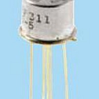
RF311-5/G
Description
RF (Radio Frequency) Relays 5V SPDT RF TO-5 High Repeat
Manufacturer
TELEDYNE
Series
RF311r
Datasheet
1.RF311-5G.pdf
(8 pages)
Specifications of RF311-5/G
Coil Resistance
63 Ohms
Frequency
8 GHz
Coil Voltage
5 VDC
Lead Free Status / RoHS Status
Lead free / RoHS Compliant


SERIES RF311 AND RF331
GENERAL ELECTRICAL SPECIFICATIONS (@25°C unless otherwise noted) (Notes 2 & 3)
OUTLINE DIMENSIONS
RF311/RF331 Page 2
DETAILED ELECTRICAL SPECIFICATIONS (@25°C)
GENERAL NOTES
1. Relay contacts will exhibit no chatter in excess of 10 µsec or transfer in excess of 1 µsec.
2. “Typical” characteristics are based on available data and are best estimates. No on-
3. Unless otherwise specified, parameters are initial values.
4. Leads are 0.75 standard. To order 0.187 leads, add /S to the base part number.
Contact Arrangement
Rated Duty
Contact Resistance
Contact Load Ratings (DC)
Contact Life Ratings
Coil Operating Power
Operate Time
Release Time
Intercontact Capacitance
Insulation Resistance
Dielectric Strength
BASE PART NUMBERS
Coil Voltage (Vdc)
Coil Resistance (Ohms ± 20%)
Pick-up Voltage (Vdc max.)
going verification tests are performed.
Ex. RF311-5/S.
DIA. MAX.
DIA. MAX.
.017 (.43) –.001 (.03) DIA.
(9.40)
(8.51)
.370
.335
CASE DETAIL
+.002 (.05)
H
WIRE LEAD: .75 (19.05) MIN.
PIN: .187 (4.75) .010 (.25)
RF311: .275 (6.99)
RF331: .385 (9.78)
GOLD-PLATED
(NOTE 4)
H DIMENSION
SHOWN IN INCHES
DIMENSIONS ARE
(MILLIMETERS)
Nom.
SPECIFICATIONS ARE SUBJECT TO CHANGE WITHOUT NOTICE
1 Form C (SPDT)
Continuous
0.15
Resistive: 1A @ 28V dc
Low level: 10 to 50 µA @ 10 to 50 mV
10,000,000 cycles (typical) at low level
RF311: 350 mW typical @ nominal rated voltage
RF331: 185 mW typical @ nominal rated voltage
RF311: 4.0 mS max.
RF331: 6.0 mS max.
RF311: 3.0 mS max.
RF331: 3.0 mS max.
0.4 pf typical
1,000 M
Atmospheric pressure: 350 Vrms (60 Hz)
RF311
RF331
RF311
RF331
.010 (0.25)
.035 (.89)
max. initial (measured 1/8 (3.2mm) from header)
LEAD & PIN LOCATIONS
(Viewed from Terminals)
45
min. between mutually isolated terminals
TYP.
3
RF311-5/RF331-5
125
5.0
3.6
3.6
.031 (.79)
63
.003 (0.08)
5 LEADS
.200 (5.08)
.010 (.25) DIA.
(For reference only)
4
3
PIN NUMBERS
RF311-12/RF331-12
5
1025
12.0
500
9.0
9.0
2
1
SCHEMATIC DIAGRAM
(TERMINAL VIEW)
© 2007 TELEDYNE RELAYS
RF311-26/RF331-26
RF311RF331\022007\Q1
2000
4000
26.5
18.0
18.0
Related parts for RF311-5/G
Image
Part Number
Description
Manufacturer
Datasheet
Request
R

Part Number:
Description:
RF (Radio Frequency) Relays 26V SPDT RF TO-5 High Repeat
Manufacturer:
TELEDYNE
Datasheet:
Part Number:
Description:
RF (Radio Frequency) Relays 12V SPDT RF TO-5 High Repeat
Manufacturer:
TELEDYNE
Datasheet:

Part Number:
Description:
Series Designation Rf311 Rf331 Relay Type Spdt Rf To-5 Relay Sensitive, Spdt Rf To-5 Relay
Manufacturer:
Teledyne Technologies Incorporated.
Datasheet:
Part Number:
Description:
Relay; E-Mech; Freq (RF); DPDT; Cur-Rtg 1A; Ctrl-V 5DC; Vol-Rtg 28DC; PCB Mnt; 10 Pin
Manufacturer:
TELEDYNE
Datasheet:
Part Number:
Description:
Module; Thru Hole; Solid-State; 3.5 mA @ 115 V (RMS), 3.0 mA @ 220 V (RMS); 7
Manufacturer:
TELEDYNE
Datasheet:
Part Number:
Description:
Module; Thru Hole; Solid-State; 15 mA (Max.); 3.8 to 16 V (RMS); 3 VDC (Min.)
Manufacturer:
TELEDYNE
Datasheet: