276XAXH-24D Magnecraft / Schneider Electric, 276XAXH-24D Datasheet - Page 25
276XAXH-24D
Manufacturer Part Number
276XAXH-24D
Description
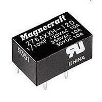
Low Signal Relays - PCB SPDT MINATURE 24V
Manufacturer
Magnecraft / Schneider Electric
Specifications of 276XAXH-24D
Coil Type
Non-Latching
Contact Form
1 Form C (SPDT)
Coil Voltage
24 VDC
Power Consumption
0.2 W
Termination Style
PCB Pins
Maximum Switching Current
7 A
Relay Type
Power
Coil Voltage Vdc Nom
24V
Contact Current Max
7A
Contact Voltage Ac Nom
240V
Contact Voltage Dc Nom
30V
Coil Resistance
2880ohm
Contact Configuration
SPDT
Current, Rating
7 A
Dielectric Rating
2000 V (RMS)
Function
Power
Mounting Type
PCB
Number Of Pins
5
Resistance, Coil
± 10 %
Standards
UL, RoHS
Temperature, Operating, Maximum
-40 to +70 °C
Termination
Solder
Voltage, Control
24 VDC
Voltage, Rating
240 VAC
Lead Free Status / RoHS Status
Lead free / RoHS Compliant
Lead Free Status / RoHS Status
Lead free / RoHS Compliant, Lead free / RoHS Compliant
Available stocks
Company
Part Number
Manufacturer
Quantity
Price
Company:

Part Number:
276XAXH-24D
Manufacturer:
MGC
Quantity:
2 119


Application Data
Typical Electromechanical PCB Relay
ARMATURE
COIL
Electromechanical PCB Relays vs. Reed Relays
MECHANICAL
CONTACTS
Magnecraft
Introduction
Printed circuit board (PCB) relays are compact relay devices used for power
management in control system designs which require the relay to be mounted
directly on the printed circuit board� They are used in applications where the relay
must be small enough to be mounted on a printed circuit board� They must be easy
to manufacture with the same machinery used in the printed circuit board line�
How Electromechanical PCB Relays Work
Electromechanical PCB relays consist of a coil, armature and contacts (see figure
below)� When power is applied to the coil, the resulting magnetic field causes the
armature to move and the contacts to open or close�
Advantages
„
„
„
How Reed Relays Work
Reed relays consist of a coil wrapped around a sealed glass tube containing the
reeds and contacts (see figure below)� When power is applied to the coil, the
resulting magnetic field causes the reeds to move and the contacts to close (1)�
Advantages
„
„
„
(1) Note that it is important to keep reed relays at a proper distance from each other because of
the possibility of magnetic-interaction between them. Proper magnetic shielding must be used
to contain stray magnetic fields. When installing reed relays into equipment, be aware of the
devices in the equipment which can produce magnetic fields. Position the relays as far away as
possible from any stray magnetic fields, and shield them to prevent false operations. A general
rule is to space reed relays no closer together than 0.5 inches.
Higher contact ratings than reed relays and smaller than traditional plug-in relays
A wider range of form, fit and function than reed relays
UL recognized to meet industry standards for product safety and compliance
Highly reliable due to longer mechanical and electrical life than
electromechanical relays
Can switch about ten times faster than an electromechanical relay with
similar ratings
Small, industry standard packaging which does not require unique machinery
to populate
Typical Reed Relay
®
PCB & Reed Relays
GLASS TUBE
CONTACTS
REEDS
COIL
25
Related parts for 276XAXH-24D
Image
Part Number
Description
Manufacturer
Datasheet
Request
R

Part Number:
Description:
Low Signal Relays - PCB SPDT MINATURE 12V
Manufacturer:
Magnecraft / Schneider Electric
Datasheet:
Part Number:
Description:
Low Signal Relays - PCB SPDT MINATURE 5V
Manufacturer:
Magnecraft / Schneider Electric
Datasheet:

Part Number:
Description:
POWER RELAY, SPDT, 6VDC, 7A, PC BOARD
Manufacturer:
Magnecraft / Schneider Electric
Datasheet:

Part Number:
Description:
TRANSFORMER POWER, 150VA, 115VAC, 60HZ
Manufacturer:
Hammond Manufacturing
Datasheet:

Part Number:
Description:
Solid State Relays 3A/50VAC SPST-NO
Manufacturer:
Magnecraft / Schneider Electric
Datasheet:

Part Number:
Description:
HEAT SINK MAGNECRAFT
Manufacturer:
Magnecraft / Schneider Electric
Datasheet:

Part Number:
Description:
Bracket, Panel Mounting; Use with 711, 712, TDRSRX/SOX Series Magnecraft Relays
Manufacturer:
Magnecraft/Schneider Electric
Datasheet:
Part Number:
Description:
Bracket, DIN Rail Mounting; Use with 711, 712, TDRSRX/SOX Series Magnecraft Relays
Manufacturer:
Magnecraft/Schneider Electric
Datasheet:

Part Number:
Description:
Solid State Relays SPST-NO 48 to 480 VAC
Manufacturer:
Magnecraft / Schneider Electric
Datasheet:
Part Number:
Description:
Solid State Relays SPST-NO 48 to 480 VAC
Manufacturer:
Magnecraft / Schneider Electric
Datasheet:
Part Number:
Description:
Solid State Relays SPST-NO 3 to 50 VDC
Manufacturer:
Magnecraft / Schneider Electric
Datasheet:
Part Number:
Description:
Solid State Relays SPST-NO 48 to 600 VAC
Manufacturer:
Magnecraft / Schneider Electric
Datasheet:
Part Number:
Description:
Solid State Relays SPST-NO 3 to 150 VDC
Manufacturer:
Magnecraft / Schneider Electric
Datasheet:
Part Number:
Description:
Solid State Relays SPST-NO 48 to 600 VAC
Manufacturer:
Magnecraft / Schneider Electric
Datasheet:
Part Number:
Description:
Relay; E-Mech; Power; On Delay; SPDT; Cur-Rtg 15A; Ctrl-V 120AC; Vol-Rtg 240/24AC/DC
Manufacturer:
Magnecraft/Schneider Electric
Datasheet: