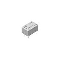
ARS114H Panasonic, ARS114H Datasheet - Page 7

ARS114H
Manufacturer Part Number
ARS114H
Description
Low Signal Relays - PCB 500MA SPST 4.5VDC LATCHING PCB
Manufacturer
Panasonic
Datasheet
1.ARS14A12.pdf
(11 pages)
Specifications of ARS114H
Contact Form
1 Form C
Coil Voltage
4.5 VDC
Coil Current
44.4 mA
Coil Type
Single Latching
Power Consumption
200 mW
Contact Carry Current
500 mA
Termination Style
Solder Terminal
Isolation
30 dB at 3 GHz
Insertion Loss
0.3 dB at 3 GHz
Maximum Switching Current
500 mA
Contact Rating
500 mA
Lead Free Status / RoHS Status
Lead free / RoHS Compliant
2. 75Ω type
Schematic (Bottom view)
1. Standard contact type
<Surface-mount terminal>
1. Impedance: 50Ω type
1) E layout
(Deenergized condition)
Single side stable type
CAD Data
Direction indication
NC
–
10
1
9
COM
8
7
NO
+
6
5
Direction indication
1 coil latching type
RESET
(Reset condition)
The part numbers
depend on the
type and voltage.
+
10
The part numbers depend
on the type and voltage.
1
9
COM
8
3.2
0.6
External dimensions
All Rights Reserved © COPYRIGHT Panasonic Electric Works Co., Ltd.
8-0.4
8-.016
7
.126
.024
SET
0.5
.020
3.2
.126
–
3-0.40×0.20
3-.016×.008
6
5
3- 0.45
3- .018
14.0
10.16
10.16
.400
.400
14.6
.575
External dimensions
Direction indication
2.54
.100
2 coil latching type
.551
(Reset condition)
RESET COM
JAPAN
–
10
1
(1.40)
(.055)
0.5
0.5
1.27
3.2
14.00
0.6
3.2
0.6
Lot No.
.551
9
8.0
.315
Tolerance: ±0.3
.020
.020
.126
.024
.126
.024
8
.050
JAPAN
0.15
.006
7
+
2 coil latching only
4
SET
+
2-1.40×0.20
2-.055×.008
Lot No.
6
5
Stand off
Tolerance: ±0.3
11.2
.441
.339
.362
9.2
8.6
0.15
.006
±.012
6.35
.250
8.60
.339
2. Reversed contact type
(Deenergized condition)
Single side stable type
<Standard contact type>
<Reversed contact type>
Schematic (Top view)
Direction indication
(Deenergized condition)
(Deenergized condition)
±.012
1.40
.055
Single side stable type
Single side stable type
NO
–
Direction indication
Direction indication
10
1
18
NO
18 17
NC
9
17
-
-
2
2
COM
16
16
8
15
COM
COM
15
4
4
14 13
7
14
6
13
6
NC
+
12
12
NO
NC
6
7
7
5
11
+
11 10
+
8
8
10
3-0.70 dia. Min.
3-.028 dia. Min.
PC board pattern (Bottom view)
3-0.90 dia.
3-.035 dia.
Direction indication
1 coil latching type
(Reset condition)
SET
+
10
1 coil latching type
Direction indication
1 coil latching type
Direction indication
1
(Reset condition)
(Reset condition)
9
RESET
18 17
SET
18 17
COM
2
+
+
2
16
16
8
COM
15
COM
15
4
4
7
2.54
.100
14
14
RESET
13
13
6
6
–
6
RESET
5
12
12
SET
7
7
11 10
-
11 10
-
8
8
1.80
.071
Direction indication
2 coil latching type
2 coil latching only
(Reset condition)
Tolerance: ±0.1
SET
RS (ARS)
–
10
R0.40
R.016
1
Direction indication
Direction indication
2-coil latching type
2-coil latching type
(Reset condition)
(Reset condition)
9
RESET
18 17
18 17
SET
COM
-
-
2
2
8
16
16
15
COM
15
COM
4
4
7
+
RESET
14
14
4
13
13
+
6
6
6
5
12
RESET
12
SET
+
+
7
7
±.004
11 10
+
11 10
+
8
8


