G6K-2F-RF-DC3 Omron, G6K-2F-RF-DC3 Datasheet - Page 6
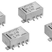
G6K-2F-RF-DC3
Manufacturer Part Number
G6K-2F-RF-DC3
Description
Low Signal Relays - PCB 1GHz DPDT 3VDC
Manufacturer
Omron
Series
G6KRFr
Datasheet
1.G6K-2F-RF-S-DC5.pdf
(8 pages)
Specifications of G6K-2F-RF-DC3
Coil Type
Non-Latching
Coil Current
33 mA
Contact Form
2 Form C
Coil Voltage
3 VDC
Power Consumption
100 mW
Termination Style
Solder Terminal
Isolation
20 dB to 30 dB at 1 GHz
Insertion Loss
0.2 dB at 1 GHz
Maximum Switching Current
1 A
Contact Rating
0.3 A at 125 VAC, 1 A at 30 VDC
Contact Configuration
DPDT
Contact Current Max
1A
Contact Voltage Ac Nom
125V
Contact Voltage Dc Nom
30V
Coil Voltage Vdc Nom
3V
Coil Frequency Max
1GHz
Coil Resistance
91ohm
Rohs Compliant
Yes
Lead Free Status / RoHS Status
Lead free / RoHS Compliant
Lead Free Status / RoHS Status
Lead free / RoHS Compliant, Lead free / RoHS Compliant
Other names
3DC G6K-2F-RF


Precautions
■ Recommended Soldering Method
1. Temperature Profile for Lead Solder (Measured at the PCB)
3. The thickness of cream solder to be applied should be between 200 and 250 μm and the land pattern should be based on Omron’s recommended
■ Precautions for correct use
For general precautions, refer to Omron’s Relay Technical guidelines, contained in Omron’s relay catalog.
Relay Handling
Do not unpack the relay until ready to mount it. Use the relay as soon as
possible after opening the moisture-proof bag. Otherwise, the terminals
may tarnish and seal failure may occur after the solder process.
When washing the product after soldering, use a water-based or
alcohol-based solvent. Keep the solvent temperature below 40°C.
Do not put the relay in a cold cleaning bath immediately after soldering.
Operating, Storage Environment
If the relay is stored for a long time in an adverse environment with high
temperature, high humidity, organic or sulfide gases, then sulfide or
oxide films will form on the contact surfaces. These films may result in
unstable contact, contact problems or function problems. Therefore,
operate, store or transport the product under specified environmental
conditions.
Coating
The relay mounted on the PCB may be coated or washed, but do not
apply silicone coating or detergent containing silicone, otherwise, the
silicone coating or detergent may remain on the surface of the relay.
Latching Relay Mounting
Make sure that excess vibration or shock doesn’t set or reset the
relay during normal operation. The relay is shipped in the ‘reset’
position. Shock or vibration during shipping may require the application
of a reset signal, prior to operation.
326
PCB pattern. To maintain the correct soldering joint shown in the following diagram, we recommend applying solder using the soldering conditions
shown above. Check the soldering in the actual mounting conditions prior to use.
1. Use in locations where the relay is not exposed to corrosive
2. Use in locations where no visible dust exists.
3. Use in locations where the product is not exposed to direct
4. Do not apply force to the product which may result in deformation
gas such as hydrogen sulfide gas or salty air.
sunlight, rain or snow.
or change in quality of the product.
220 to
180 to
High Frequency Relay
245
200
150
Preheating
90 to 120
PCB
Soldering
20 to 30
G6K-RF
Terminal
Time (s)
Relay
Solder
Land
2. Temperature Profile for Lead-free Solder (Measured at the PCB)
Claw Securing Force During Automatic Mounting
During automatic insertion of relays, make sure to set the securing
force of each claw to the following so that the relay’s characteristics
will be maintained.
Maximum Allowable Voltage
The maximum allowable voltage of the coil can be obtained from the
coil temperature increase and the heat-resisting temperature of the
coil insulating sheath material. (Exceeding the heat-resisting tem-
perature may result in burning or short-circuiting.) The maximum
allowable voltage also involves important restrictions which include
the following;
• Must not cause thermal changes in or deterioration of the insulating
• Must not cause damage to other control devices.
• Must not cause any harmful effect on people.
• Must not cause fire.
Therefore, be sure to use the maximum allowable voltage as specified in
the catalog. As a rule, the rated voltage must be applied to the coil. A
voltage exceeding the rated value, however, can be applied to the coil
providing that the voltage is less than or equal to the maximum allowable
voltage. It must be noted that continuous voltage application to the coil
will cause a coil temperature increase which may affect characteristics
such as electrical life and coil insulation.
Consider using a latching relay instead of a non-latching relay with a
continuous voltage applied to the coil.
material, which may result in films developing on the contacts.
Insufficient
amount of
solder
C
250 max.
230
180
150
B
Secure the claws to the shaded area. Do not
attach them to the center of the relay or just
one part of the relay.
Excessive
amount of
solder
Direction A: 1.96 N max.
Direction B: 4.90 N max.
Direction C: 1.96 N max.
120 max.
Preheating
Case top panel
(peak): 255°C max.
Soldering
30 max.
Relay terminal
section
Time (s)
Related parts for G6K-2F-RF-DC3
Image
Part Number
Description
Manufacturer
Datasheet
Request
R

Part Number:
Description:
RELAY SMT DPDT 1A 5VDC T/R
Manufacturer:
Omron
Datasheet:

Part Number:
Description:
RELAY SMT DPDT 1A 5VDC T/R
Manufacturer:
Omron
Datasheet:
Part Number:
Description:
RELAY SMT DPDT 1A 12VDC T/R
Manufacturer:
Omron
Datasheet:
Part Number:
Description:
RELAY SMT DPDT 1A 12VDC T/R
Manufacturer:
Omron
Datasheet:

Part Number:
Description:
SMT TAPE-N-REEL RELAY
Manufacturer:
Omron
Datasheet:
Part Number:
Description:
SMT TAPE-N-REEL RELAY
Manufacturer:
Omron
Datasheet:

Part Number:
Description:
High Frequency Relay
Manufacturer:
Omron
Datasheet:
Part Number:
Description:
SMT TAPE-N-REEL RELAY
Manufacturer:
Omron
Datasheet:
Part Number:
Description:
SMT TAPE-N-REEL RELAY
Manufacturer:
Omron
Datasheet:
Part Number:
Description:
SMT TAPE-N-REEL RELAY
Manufacturer:
Omron
Datasheet:
Part Number:
Description:
SMT RELAY
Manufacturer:
Omron
Datasheet:
Part Number:
Description:
SMT RELAY
Manufacturer:
Omron
Datasheet:
Part Number:
Description:
SMT TAPE-N-REEL RELAY
Manufacturer:
Omron
Datasheet:
Part Number:
Description:
SMT TAPE-N-REEL RELAY
Manufacturer:
Omron
Datasheet:
Part Number:
Description:
SMT TAPE-N-REEL RELAY
Manufacturer:
Omron
Datasheet: