TXD2SS-24V Panasonic, TXD2SS-24V Datasheet - Page 12
TXD2SS-24V
Manufacturer Part Number
TXD2SS-24V
Description
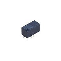
Low Signal Relays - PCB 2 Form C 2A 30VDC 24VDC
Manufacturer
Panasonic
Datasheet
1.TXD2SS-12V-Z.pdf
(12 pages)
Specifications of TXD2SS-24V
Contact Form
2 Form C
Coil Voltage
24 VDC
Coil Current
9.6 mA
Coil Type
Single Side Stable
Power Consumption
230 mW
Contact Carry Current
2 A at 30 VDC
Termination Style
Solder Pad
Isolation
20 dB at 1 GHz
Insertion Loss
0.8 dB at 1 GHz
Maximum Switching Current
2 A
Contact Rating
2 A at 30 VDC
Lead Free Status / RoHS Status
Lead free / RoHS Compliant
Available stocks
Company
Part Number
Manufacturer
Quantity
Price
Company:

Part Number:
TXD2SS-24V
Manufacturer:
PANASONIC
Quantity:
12 000


TX-D
NOTES
1. Packing style
1) Tube packing
The relay is packed in a tube with the
relay orientation mark on the left side, as
shown in the figure below.
2) Tape and reel packing (surface-mount
terminal type)
(1) Tape dimensions
(i) SA type
(ii) SL type
(iii) SS type
Stopper (gray)
Relay polarity bar
(Z type)
TX-D relays
TX-D relays
TX-D relays
Relay polarity bar
(Z type)
Relay polarity bar
(Z type)
Orientation (indicates PIN No.1) stripe
Tape coming out direction
Tape coming out direction
Tape coming out direction
.059
.059
.059
1.5
1.5
1.5
+0.1
+.004
+0.1
+.004
+0.1
+.004
0
0
0
0
0
0
dia.
dia.
dia.
dia.
dia.
dia.
16.0
.630
.630
16.0
.630
16.0
.079
.079
.079
2.0
2.0
2.0
10.0
A
.157
.157
.157
4.0
4.0
4.0
10.0
.394
.394
C
D
.315
B
8.0
11.5
.453
Stopper (green)
1.75
.069
15.5
.610
15.5
.610
24.0
.945
11.5
.453
24.0
.945
11.5
.453
24.0
.945
1.75
.069
1.75
.069
15.5
.610
mm
mm
±0.3
±.012
mm
±0.3
±.012
±0.3
±.012
10.8
.425
.362
10.8
.425
9.2
.016
.016
inch
inch
inch
0.4
0.4
.016
0.4
±0.2
±.008
±0.2
±.008
±0.2
±.008
All Rights Reserved © COPYRIGHT Panasonic Electric Works Co., Ltd.
(2) Dimensions of plastic reel
3) Ambient temperature when
transporting and during storage with the
product in its original packaging:
–40 to +70°C
2. Automatic insertion
To maintain the internal function of the
relay, the chucking pressure should not
exceed the values below.
Chucking pressure in the direction A:
4.9 N {500gf} or less
Chucking pressure in the direction B:
9.8 N {1 kgf} or less
Chucking pressure in the direction C:
9.8 N {1 kgf} or less
Please chuck the
Avoid chucking the center of the relay.
In addition, excessive chucking pressure
to the pinpoint of the relay should be
avoided.
.079
2.0
±0.5
±.020
–40 to +158°F
A
.827
.512
C
21
13
±0.6
±.024
±0.5
±.020
portion.
.961
dia.
dia.
24.4
dia.
dia.
+.079
0
+2
B
0
3.150
380
14.961
.079
80
2.0
mm
±1
±2
±0.2
dia.
±.008
±.039
dia.
±.079
inch
dia.
dia.
3. M.B.B. type
A small OFF time may be generated by
the contact bounce during contact
switching. Check the actual circuit
carefully.
If the relay is dropped accidentally, check
the appearance and characteristics
including M.B.B. time before use.
For general cautions for use,
please refer to the “Cautions for
use of Signal Relays” or “General
Application Guidelines”.
Measuring condition of M.B.B. time
5V DC
500Ω
Min. 10µs
Related parts for TXD2SS-24V
Image
Part Number
Description
Manufacturer
Datasheet
Request
R

Part Number:
Description:
RELAY 2A 12VDC 200MW SMD
Manufacturer:
Panasonic Electric Works
Datasheet:
Part Number:
Description:
RELAY 2A 24VDC 230MW SMD
Manufacturer:
Panasonic Electric Works
Datasheet:
Part Number:
Description:
RELAY 2A 5VDC 200MW SMD
Manufacturer:
Panasonic Electric Works
Datasheet:
Part Number:
Description:
RELAY 2A 12VDC 200MW SMD
Manufacturer:
Panasonic Electric Works
Datasheet:
Part Number:
Description:
RELAY 2A 5VDC 200MW SMD
Manufacturer:
Panasonic Electric Works
Datasheet:

Part Number:
Description:
RELAY LATCH 2A 4.5VDC 150MW SMD
Manufacturer:
Panasonic Electric Works
Datasheet:
Part Number:
Description:
RELAY 2A 1.5VDC 200MW SMD
Manufacturer:
Panasonic Electric Works
Datasheet:
Part Number:
Description:
RELAY 2A 3VDC 200MW SMD
Manufacturer:
Panasonic Electric Works
Datasheet:
Part Number:
Description:
RELAY 2A 9VDC 200MW SMD
Manufacturer:
Panasonic Electric Works
Datasheet:
Part Number:
Description:
RELAY LATCH 2A 4.5VDC 150MW SMD
Manufacturer:
Panasonic Electric Works
Datasheet:

Part Number:
Description:
Color CCD Linear Image Sensor with 1024 Pixels for R and B Colors/2048 Pixels for G Color
Manufacturer:
Panasonic
Datasheet:
Part Number:
Description:
2048-Bit CCD Linear Image Sensor
Manufacturer:
Panasonic
Datasheet:
Part Number:
Description:
2592-Bit CCD Linear Image Sensor
Manufacturer:
Panasonic
Datasheet:
Part Number:
Description:
2048-Bit High-Responsivity CCD Linear Image Sensor with Internal Clock Driver
Manufacturer:
Panasonic
Datasheet: