NC2EBD-P-DC12V Panasonic, NC2EBD-P-DC12V Datasheet - Page 12
NC2EBD-P-DC12V
Manufacturer Part Number
NC2EBD-P-DC12V
Description
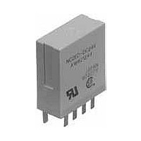
General Purpose / Industrial Relays 5A 12V DPDT AMB SEAL VERTICAL PCB
Manufacturer
Panasonic
Datasheet
1.N-TC-48.pdf
(14 pages)
Specifications of NC2EBD-P-DC12V
Contact Form
2 Form C
Coil Voltage
12 VDC
Contact Rating
5 A at 250 VAC
Coil Termination
Solder Terminal
Contact Termination
Solder Terminal
Mounting Style
Through Hole
Power Consumption
360 mW
Contact Material
Gold Clad Silver Nickel
Coil Resistance
400 Ohms
Coil Type
Single Side Stable
Lead Free Status / RoHS Status
Lead free / RoHS Compliant
Available stocks
Company
Part Number
Manufacturer
Quantity
Price
Company:

Part Number:
NC2EBD-P-DC12V
Manufacturer:
ARM
Quantity:
202


DIMENSIONS
Flat type socket
for PC board
NC2-JPS
Note: Terminals 3 and 6 excluded for NC2-JPS.
Flat type socket
for PC board
NC4-JPS
Note: Terminals 3 and 6 excluded for NC4-JPS.
Slim type
DIN terminal socket
NC2-SFD
(Retaining springs
are included with the
DIN terminal socket.)
(mm inch)
CAD Data
CAD Data
CAD Data
1.575
20.32
*To prevent damage or distortion, when tightening fixing screws, the optimum torque range should be 0.49 to 0.69 N·m, (5 to 7 kgf·cm).
.800
40
1.000
10.16
.400
25.4
15.24 0.2
.600 .008
.300 .008
.200 .008
7.62 0.2
5.08 0.2
All Rights Reserved © COPYRIGHT Panasonic Electric Works Co., Ltd.
2-3.5 dia. hole
2-.138 dia.
2-3.5 dia. hole
2-.138 dia.
.709 .024
The CAD data of the products with a
18 0.6
External dimensions
External dimensions
External dimensions
20.32 0.3
.800 .012
1.374
M3 screw
M.118
34.9
1.374
34.9
Chassis mounting pitch
67 1
2.638 .039
14.8
.583
14.8
.583
Approx.
44.3
1.744
Approx.
44.3
1.744
1.122 .024
28.5 0.6
.811 .024
20.6 0.6
27.94
1.100
27.94
1.100
35.4 0.5
1.394 .020
9
7
MADE IN
8
11
MADE IN JAPAN
10
JAPAN
6
7
CAD Data
15.24
10.16
20.32
12
.600
5
.800
5.08
.200
.400
11 12
5.08
.200
6 5 4 3
13
4 3
10.16
20.32
30.48
1.200
15.24
35.56
1.400
1.000
.600
5.08
.200
5.08
.200
.400
.800
25.4
14
13
2
Mounting hole diagram
14 15 16
2
.709 .008 .709 .008
18 0.2 18 0.2
mark can be downloaded from: http://panasonic-electric-works.net/ac
1
Terminal portion
Terminal portion
33.5
1.319
.004max
.004max
0.1max
0.1max
67
2.638
2-M3.5 screw hole
(or 4.2 0.1 dia. hole)
2-M.138 screw hole
(or .165 .004 dia. hole)
.154
.154
3.9
3.9
2.54 11
.100 11
2.54
.100
2.8 dia.
.110 dia.
2.54 11
.100 11
2.54
.100
PC board pattern
PC board pattern
2.8 dia.
.110 dia.
2.54
.100
9
Schematic
2.54
.100 .020
11
12
8
2
4
10 11
7
7
11
16-1.2 dia. hole
16-.047 dia.
6 5
0.5
.020
13
14
6 5
0.5
7
5
12 13
10-1.2 dia. hole
10-.047 dia.
12
N.C.
N.O.
4 3
COM
Coil
13
4 3
14
14
2
NC
2
15
1
16