G9EB-1-B-DC12 Omron, G9EB-1-B-DC12 Datasheet
G9EB-1-B-DC12
Specifications of G9EB-1-B-DC12


G9EB-1-B-DC12 Summary of contents
Page 1
... Note: 1. Two M4 screws are provided for the contact terminal connection. 2. Two M4 screws are provided for the coil terminal connection. Terminals Contact form Contact terminals Screw terminals SPST-NO (See note 1.) DC Power Relays (25-A Models) Coil rated voltage Model 12 VDC G9EB-1-B 24 VDC 48 VDC 60 VDC 100 VDC G9EB-1 17 ...
Page 2
... VDC 30,000 ops. min min (10 min) 100 A at 250 VDC (5 times 250 VDC (50 times min.) − ° C (with no icing or condensation 85% Approx. 135 g G9EB-1 Maximum voltage voltage (See note 3.) consumption 130% of rated volt- Approx age (at 23°C within 10 minutes) G9EB-1-B Power ...
Page 3
... Engineering Data ■ G9EB-1-B Switching/Current Conduction Models Maximum Switching Capacity 100 50 DC resistive load 100 300 500 1,000 Switching voltage (V) Carry Current vs Energizing Time 100,000 50,000 30,000 10,000 5,000 3,000 1,000 500 300 100 100 300 500 1,000 Carry current (A) Electrical Endurance ...
Page 4
... Characteristics were measured after applying vibration at a frequency (single amplitude of 0.75 mm) to the test piece (not energized) for 2 hours each in 3 directions. The percentage rate of change is the average value for all of the samples Shock Resistance 5.0 Sample: G9EB-1-B 12 VDC 4.0 Number: 5 3.0 2.0 1.0 Must-operate voltage ...
Page 5
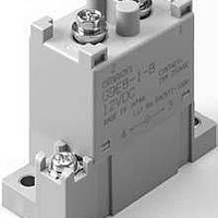
... Two, M4 49.2 (Coil M4 screw (Coil M4 screw dimensions) Two, M4 dimensions G9EB-1-B 12VDC CONTACT: 25A 250VDC MADE IN JAPAN 58 Lot No. 0424Y1-0001 18 Power Relays (25-A Models) Terminal Arrangement/ Internal Connections (TOP VIEW Mounting Hole Dimensions (TOP VIEW) Two 4.8-dia. holes 50± 0.1 13± 0.1 G9EB-1 21 ...
Page 6
... The specified tightening torque cannot be achieved with different screws and may result in abnor- mal heat generation when energized. Recommended Wire Size Model G9EA-1(- G9EA-1(-B)- G9EC-1(- G9EB-1 5.5 mm Note: Use flexible leads. Size ...