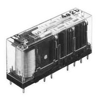
SFS6-SFD Panasonic, SFS6-SFD Datasheet - Page 3

SFS6-SFD
Manufacturer Part Number
SFS6-SFD
Description
General Purpose / Industrial Relays SFS Relay DIN Socket
Manufacturer
Panasonic
Datasheet
1.SFS2-DC12V.pdf
(8 pages)
Specifications of SFS6-SFD
Contact Form
SPDT
Mounting Style
Through Hole
Power Consumption
360 mW
Contact Material
Silver Tin Oxide
Lead Free Status / RoHS Status
Lead free / RoHS Compliant
SFS
REFERENCE DATA
1. Operate/response/release time
Tested sample: SFS4-DC24V (4 Form A/2 Form B),
20pcs. (a contacts: 80, b contacts: 40)
4. Max, switching capacity
Other contact gaps when contacts are welded
Sample: SFS4-DC24V (4 Form A/2 Form B)
The table below shows the state of the other contacts.
In case of form “NO” contact weld the coil applied voltage is 0 V.
In case of form “NC” contact weld the coil applied voltage is nominal.
Empty cells: either ON or OFF
Note: Contact gaps are shown at the initial state.
>0.5: contact gap is kept at min. 0.5 mm
Welded contact No.
If the contact transfer is caused by load switching, it is necessary to check the actual loading.
0.7
0.5
0.3
0.2
0.1
10
50
40
30
20
10
0
8
7
6
5
4
3
2
1
10
0
DC resistive load
1
20 30
2 3 4 5 6 7 8 9 10 11 12 13 14 15
AC resistive load
50 70 100
Contact voltage, V
Time, ms
11-12 (NO)
13-14 (NO)
9-10 (NO)
125
7-8 (NO)
3-4 (NC)
5-6 (NC)
200 300 500
Operate time
Release time
Response time
250
.020inch
1000
3-4 (NC)
All Rights Reserved © COPYRIGHT Panasonic Electric Works Co., Ltd.
>0.5
>0.5
>0.5
>0.5
2. Coil temperature rise
Tested sample: SFS4-DC24V (4 Form A/2 Form B),
3pcs.
Measured portion: Inside the coil
Ambient temperature: Room temperature
(27 C
80.6
50
40
30
20
10
0
90
5-6 (NC)
F), 70 C
>0.5
>0.5
>0.5
>0.5
100
158
Coil applied voltage, %V
F, 85 C
110
0A Room temperature
6A Room temperature
0A 70 C
6A 70 C
0A 85 C
4.5A 85 C
7-8 (NO)
185 F
>0.5
>0.5
State of other contacts
120
130
9-10 (NO)
>0.5
>0.5
3. Malfunctional shock
Tested sample: SFS4-DC24V (4 Form A/2 Form B),
3pcs.
200m/s
200m/s
Y
Y'
Z'
Z'
X
11-12 (NO)
Z
2
2
X
>0.5
>0.5
X'
Deenergized condition
Energized condition
Y'
Y
200m/s
200m/s
2
2
13-14 (NO)
200m/s
200m/s
>0.5
>0.5
X'
Z
2
2


