G9EC-1-DC12 Omron, G9EC-1-DC12 Datasheet - Page 20
G9EC-1-DC12
Manufacturer Part Number
G9EC-1-DC12
Description
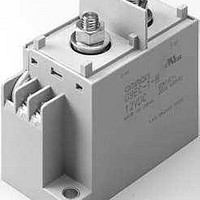
General Purpose / Industrial Relays 12VDC 200A LEAD WIRE
Manufacturer
Omron
Series
G9ECr
Datasheet
1.G9EA-1-B-CA-DC12.pdf
(24 pages)
Specifications of G9EC-1-DC12
Contact Form
SPST - NO
Coil Voltage
12 VDC
Contact Rating
200 A
Coil Termination
Lead Wires
Contact Termination
Screw
Power Consumption
11 W
Coil Current
938 mA
Coil Resistance
12.8 Ohms
Lead Free Status / RoHS Status
Lead free / RoHS Compliant


20
0.9
0.8
0.7
0.6
0.5
0.4
0.3
0.2
0.1
1
0
Vibration Malfunction
1
Unit: m/s
Sample: G9EB-1-B
Number: 5
Sample: G9EB-1-B 12 VDC
Number: 5
Shock Malfunction
Deenergized
The value at which malfunction occurred was
measured after applying shock to the test piece
3 times each in 6 directions along 3 axes.
Z'
X
2
12 VDC
DC Power Relays (25-A Models)
3
Energized
5
Unconfirmed area
Confirmed area
0
10
Y'
Y
150
100
50
50
100
150
200
200
Frequency (Hz)
Y'
30
Y
50
X'
Z
X
X'
100
Z
Z'
−1.0
−2.0
−3.0
−4.0
−5.0
−1.0
−2.0
−3.0
−4.0
−5.0
5.0
4.0
3.0
2.0
1.0
0.0
5.0
4.0
3.0
2.0
1.0
0.0
Shock Resistance
Characteristics were measured
of 490 m
along 3 axes
average value for all of the samples.
Start
Vibration Resistance
Characteristics were measured after applying vibration
at a frequency of 10 to 55 Hz (single amplitude of 0.75
mm) to the test piece (not energized) for 2 hours each
in 3 directions. The percentage rate of change is the
average value for all of the samples
Start
Sample: G9EB-1-B 12 VDC
Number: 5
Sample: G9EB-1-B 12 VDC
Number: 5
G9EB-1
2
/s to the test piece 3 times each in 6 directions
. The percentage rate of change is the
Must-release voltage
Must-operate voltage
Must-operate voltage
Must-release voltage
after applying a shock
After test
After test