CM1-12V Panasonic, CM1-12V Datasheet - Page 5
CM1-12V
Manufacturer Part Number
CM1-12V
Description
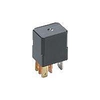
General Purpose / Industrial Relays 35A 12VDC 1 FORM C SEALED PLUG-IN
Manufacturer
Panasonic
Datasheet
1.CM1A-12V.pdf
(5 pages)
Specifications of CM1-12V
Contact Form
1 Form C
Coil Voltage
12 VDC
Contact Rating
35 A at 14 VDC, 20 A at 14 VDC
Coil Termination
Quick Connect
Contact Termination
Quick Connect
Mounting Style
Plug-In
Power Consumption
1.5 W
Contact Material
Silver Alloy
Coil Current
125 mA
Coil Resistance
96 Ohms
Coil Type
Standard
Lead Free Status / RoHS Status
Lead free / RoHS Compliant
Available stocks
Company
Part Number
Manufacturer
Quantity
Price
Company:

Part Number:
CM1-12V
Manufacturer:
PANASONIC
Quantity:
12 000


8-(1). Electrical life test (Motor free)
Sample: CM1aF-R-12V, 6pcs.
Load: 16 A 13.5 V DC
Cooling fan motor actual load (free condition)
Switching frequency: (ON:OFF = 2s:6s)
Ambient temperature: Room temperature
Circuit
Load current waveform
Inrush current: 85A, Steady current: 18A,
8-(2). Electrical life test (Halogen lamp load)
Sample: CM1aF-R-12V, 6pcs.
Load: 20A 13.5V DC
Switching frequency: (ON:OFF = 1s:14s)
Ambient temperature: Room temperature
Cautions regarding the protection element
1. Part numbers without protection
elements
1) 12 V models
When connecting a coil surge protection
circuit to these relays, we recommend a
Zener diode with a Zener voltage of 24 V
or higher, or a resistor (680Ω to 1,000Ω).
When a diode is connected to the coil in
parallel, the release time will slow down
and working life may shorten. Before use,
please check the circuit and verify that
the diode is not connected in parallel to
the coil drive circuit.
2) 24 V models
When connecting a coil surge protection
For Cautions for Use, see Relay Technical Information.
Discontinued as of August 31, 2010
13.5V
Cooling fan motor
M
20A
500ms
All Rights Reserved © COPYRIGHT Panasonic Electric Works Co., Ltd.
M
Change of pick-up and drop-out voltage
Change of pick-up and drop-out voltage
circuit to these relays, we recommend a
Zener diode with a Zener voltage of 48 V
or higher, or a resistor (2,800Ω to
4,700Ω).
When a diode is connected to the coil in
parallel, the release time will slow down
and working life may shorten. Before use,
please check the circuit and verify that
the diode is not connected in parallel to
the coil drive circuit.
2. Part numbers with diodes
These relays use a diode in the coil surge
protection element. Therefore, the
release time is slower and the working life
might be shorter compared to part
10
10
9
8
7
6
5
4
3
2
1
0
9
8
7
6
5
4
3
2
1
0
0
0
10
Drop-out voltage
No. of operations, × 10
Drop-out voltage
Pick-up voltage
No. of operations, × 10
Pick-up voltage
5
20
4
4
35
10
Max.
Min.
Max.
Min.
Max.
Min.
Max.
Min.
Change of contact resistance
Change of contact resistance
numbers without protection elements and
part numbers with resistors.
Be sure to use only after evaluating under
actual load conditions.
3. Part numbers with resistors
This part number employs a resistor in
the coil surge protection circuit; therefore,
an external surge protection element is
not required. In particular, when a diode
is connected in parallel with a coil, the
revert time becomes slower which could
adversely affect working life. Please
check the circuit and make sure that a
diode is not connected in parallel with the
coil drive circuit.
10
10
9
8
7
6
5
4
3
2
1
0
9
8
7
6
5
4
3
2
1
0
0
0
10
No. of operations, × 10
No. of operations, × 10
5
20
4
4
35
10
CM
Max.
X
Min.
Max.
X
Min.