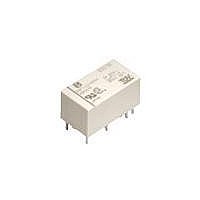
DSP2A-DC12V Panasonic, DSP2A-DC12V Datasheet - Page 4

DSP2A-DC12V
Manufacturer Part Number
DSP2A-DC12V
Description
General Purpose / Industrial Relays 5A 12VDC DPST NO SEALED
Manufacturer
Panasonic
Datasheet
1.DSP1A-DC9V.pdf
(7 pages)
Specifications of DSP2A-DC12V
Contact Form
2 Form A
Coil Voltage
12 VDC
Contact Rating
5 A at 250 VAC, 5 A at 30 VDC
Coil Termination
Solder Terminal
Contact Termination
Solder Terminal
Mounting Style
Through Hole
Power Consumption
300 mW
Contact Material
Gold Flashed Silver Tin Oxide
Coil Current
25 mA
Coil Resistance
480 Ohms
Coil Type
Single Side Stable
Lead Free Status / RoHS Status
Lead free / RoHS Compliant
Available stocks
Company
Part Number
Manufacturer
Quantity
Price
Company:
Part Number:
DSP2A-DC12V
Manufacturer:
TAKAMIS
Quantity:
5 400
Part Number:
DSP2A-DC12V
Manufacturer:
PANASONIC/松下
Quantity:
20 000
Company:
Part Number:
DSP2A-DC12V-F
Manufacturer:
NAIS/PANASONIC
Quantity:
20 000
DSP
4.-(1) Operate & release time
(without diode, 1 Form A)
Tested sample: DSP1a-DC12V, 5 pcs.
4.-(4) Operate & release time
(with diode, 1 Form A)
Tested sample: DSP1a-DC12V, 5 pcs.
5.-(1) Change of pick-up and drop-out voltage
(1 Form A)
Tested sample: DSP1a-DC12V, 5 pcs.
6.-(1) Influence of adjacent mounting
(1 Form A)
Tested sample: DSP1a-DC12V, 5 pcs.
15
10
15
10
9
8
7
6
5
4
3
2
1
0
5
5
7
6
5
4
3
2
1
0
0
–40 –20
80
80
Pick-up voltage
Drop-out voltage
Coil applied voltage, %V
Coil applied voltage, %V
Inter-relay distance ( ), mm
0
5
Release time
100
100
–50
50
20 40
Operate time
Operate time
Release time
Pick-up voltage
60
Ambient
temperature, C
10
A, C
relays
are not
energized
A, C
relays
are
energized
A
Drop-out
voltage
120
80
120
B
Max.
x
Min.
Max.
x
Min.
Max.
x
Min.
Max.
x
Min.
C
All Rights Reserved © COPYRIGHT Panasonic Electric Works Co., Ltd.
4.-(2) Operate & release time
(without diode, 1 Form A 1 Form B)
Tested sample: DSP1-DC12V, 5 pcs.
4.-(5) Operate & release time
(with diode, 1 Form A 1 Form B)
Tested sample: DSP1-DC12V, 5 pcs.
5.-(2) Change of pick-up and drop-out voltage
(1 Form A 1 Form B)
Tested sample: DSP1-DC12V, 5 pcs.
6.-(2) Influence of adjacent mounting
(1 Form A 1 Form B)
Tested sample: DSP1-DC12V, 5 pcs.
–10
10
–2
–4
–6
–8
8
6
4
2
0
0
9
8
7
6
5
4
3
2
1
0
9
8
7
6
5
4
3
2
1
0
Drop-out voltage
–40 –20
1
80
80
2
Pick-up voltage
Drop-out voltage
Release time
Coil applied voltage, %V
3
Coil applied voltage, %V
Inter-relay distance ( ), mm
0
Release time
4
Operate time
Operate time
100
100
50
20 40
–50
5
Pick-up voltage
6
110
110
Ambient
temperature, C
Max.
Min.
Max.
Min.
60
x
x
Max.
Max.
x
x
Min.
Min.
A, C
relays
are not
energized
A, C
relays
are
energized
A
80
B
C
4.-(3) Operate & release time
(without diode, 2 Form A)
Tested sample: DSP2a-DC12V, 5 pcs.)
4.-(6) Operate & release time
(with diode, 2 Form A)
Tested sample: DSP2a-DC12V, 5 pcs.
5.-(3) Change of pick-up and drop-out voltage
(2 Form A)
Tested sample: DSP2a-DC12V, 5 pcs.
6.-(3) Influence of adjacent mounting
(2 Form A)
Tested sample: DSP2a-DC12V, 5 pcs.
15
10
15
10
5
5
9
8
7
6
5
4
3
2
1
0
9
8
7
6
5
4
3
2
1
0
0
–40 –20
80
80
Pick-up voltage
Drop-out voltage
Coil applied voltage, %V
Coil applied voltage, %V
Inter-relay distance ( ), mm
0
5
Release time
Release time
Operate time
Operate time
100
100
20 40
50
–50
Pick-up voltage
Ambient
temperature, C
60
10
A, C
relays
are not
energized
A, C
relays
are
energized
A
Drop-out
voltage
120
80
120
B
Max.
x
Min.
Max.
x
Min.
Max.
Min.
Max.
Min.
x
x
C


