HE1AN-S-AC120V Panasonic, HE1AN-S-AC120V Datasheet - Page 8
HE1AN-S-AC120V
Manufacturer Part Number
HE1AN-S-AC120V
Description
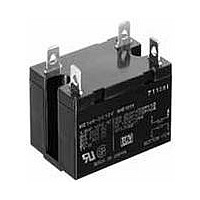
General Purpose / Industrial Relays 30A 120VAC SPST-NO SCREW
Manufacturer
Panasonic
Datasheet
1.HE1AN-P-DC48V.pdf
(9 pages)
Specifications of HE1AN-S-AC120V
Contact Form
1 Form A
Coil Voltage
120 VAC
Contact Rating
30 A at 277 VAC
Coil Termination
Screw
Contact Termination
Screw
Mounting Style
Screw
Power Consumption
2.7 VA
Contact Material
Silver Tin Oxide
Coil Current
22.1 mA
Coil Resistance
5.2 K Ohms
Coil Type
Standard
Lead Free Status / RoHS Status
Lead free / RoHS Compliant


DIMENSIONS
1 Form A and 2 Form A types
Note: The JH1-SF (1 Form A single side stable type) does not have receptacles (tooth rests) for numbers 2, 3, 7, and 8.
CAD Data
The JH2-SF (2 Form A single side stable type) does not have receptacles (tooth rests) for numbers 7 and 8.
(mm inch)
All Rights Reserved © COPYRIGHT Panasonic Electric Works Co., Ltd.
2.362
60
.354
.354
9
.866
9
22
The CAD data of the products with a
.283
7.2
.157
8
5
7
6
4
M3.5 4 screw
M.138 4
External dimensions
FEATURES
1. Snap-in mounting to DIN rails is
possible.
Can be inserted into 35 mm wide DIN
rails. Removal is easy, too.
2. Sure and easy wiring
The use of UP terminals makes wiring
exceptionally easy and sure.
TYPES
Standard packing: Carton: 10 pcs.; Case: 50 pcs.
SPECIFICATIONS
Note: Do not insert or remove while powered on.
Arrangement
Max. continuous current
Breakdown voltage (initial)
Insulation resistance
Heat resistance
10.25 8.4
.404 .331
1.339
2.756
34
70
For 1 Form A
For 2 Form A
No. of poles
(Terminal sockets)
Item
ACCESSORIES
4
3
2
1
.362
M4 4 screw
M.157 4
9.2
14.4
.567
11
.433
11
.433
CAD Data
Lot No.
1 Form A
30A 250V AC
2,000 Vrms for 1min (between terminals) (Detection current: 10mA.)
Min. 100M (between poles)
150 C 3 C for 1 hour
.906
23
.630
16
Single side stable type
mark can be downloaded from: http://panasonic-electric-works.net/ac
HE RELAY ACCESSORIES
Types
3. Hold-down clips can be stored in
main unit
Because the hold-down clips can be
stored in the main unit, there is no need
to remove them when, for example,
wiring is changed.
TERMINAL SOCKET
Specifications
Relay mounting diagram
HE RELAY
2 Form A
20A 250V AC
Panel cutout
2.402
61
2-4.2 dia. hole
(or 2-M4 screw hole)
2-.165 dia. hole
(or 2-M.157 screw hole)
40
1.575
Part No.
JH1-SF
JH2-SF