ABF.00.250.CTA LEMO, ABF.00.250.CTA Datasheet - Page 59
ABF.00.250.CTA
Manufacturer Part Number
ABF.00.250.CTA
Description
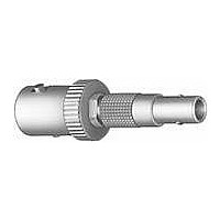
RF Connectors BNC ADAPTER 50 OHM
Manufacturer
LEMO
Datasheet
1.GCA.00.255.LT.pdf
(64 pages)
Specifications of ABF.00.250.CTA
Body Style
Adapter
Connector Type
Adapter
Features
IP rating 50
Housing Material
Brass
Length
36 mm
Mounting Angle
Straight
Operating Temperature Range
- 55 C to + 260 C
Rf Series
Between Series
Product
Adapters
Gender
Male, Female
Polarity
Normal
Shell Plating
Chrome
Impedance
50 Ohms
Termination Style
Quick Connect
Convert From
LEMO Plug
Convert To
BNC Receptacle
Lead Free Status / RoHS Status
Lead free / RoHS Compliant


Materials and Treatments
Notes: the standard surface treatments are as follows:
– Nickel FS QQ-N-290A or MIL-C-26074C
– Gold ISO 4523
Solder Contacts
The conductor bucket of these contacts is machined at
an angle to form a cup into which the solder can flow.
Design is compatible with the use of lead-free solder.
Crimp Contacts
The square form crimp method is used (MIL-C-22520F,
type 2) (photo 1).
The crimp method requires a controlled compression to
obtain a symmetrical deformation of the conductor
strand and of the contact material. The radial hole in the
side of the contact enables correct positioning of the
conductor within the contact to be verified. A good
crimping is characterized by a small conductor section
reduction and by the quite closed free spaces.
The LEMO crimp contacts are factory annealed to relieve
internal stresses, and reduce the risk of the material
work hardening during the crimping process.
During this process, an induction heating machine
designed by LEMO’s Research and Development
Department is used (photo 2).
www.lemo.com
Au
Ni
Cu
Bronze
1
ø 0.6
ø 0.6
2
1)
Features of the LEMO crimp contacts:
– Quick and simple assembly
– Insulator is not heated during contact
– High temperature applications possible
– Increased conductor retention force
Print contacts
Print contacts are available in certain connectors versions,
mostly for the straight or elbow sockets models. Connec-
tion is made on flexible or rigid printed circuits by sol-
dering
Contact Resistance in Relation to Numbers of Mating
Cycles (mesured according to IEC 605/2-2 test 2a)
Thickness comparison between the outside
and the inside of female contacts
Male solder
Male crimp
Male print
Female solder
Female crimp
Female print
minimum value
cycles
to conductor assembly
1000
male
(µm)
5.6
1.0
Contact resistance (mΩ)
Type
Gold thickness
outside
cycles
3000
(µm)
5.7
1.5
female
Brass (UNS C 38500)
Brass (UNS C 34500)
Brass (UNS C 38500)
(UNS C 54400)
Bronze
Material (Standard)
2.5
2.5
cycles
inside
5000
(%)
6.1
70
A
A
Maximum values mesured after the
mating cycles and the salt spray
test according to IEC 60512-6 test
11f.
A = inspection point
0.5
0.5
Surface treatment (µm)
Cu
Ni
3
3
®
1.0
1.5
Au
1)
57
®
Related parts for ABF.00.250.CTA
Image
Part Number
Description
Manufacturer
Datasheet
Request
R

Part Number:
Description:
RF Connectors ADAPTOR SOCKET TO BNC PLUG
Manufacturer:
LEMO
Datasheet:

Part Number:
Description:
RF Connectors ADAPT-BNC(UG88U)COAX
Manufacturer:
LEMO
Datasheet:

Part Number:
Description:
LEMO, SPRING LOADED DUSTCAP
Manufacturer:
LEMO
Datasheet:

Part Number:
Description:
Circular Push Pull Connectors CONNECTOR WRENCH FOR LEMO
Manufacturer:
LEMO
Part Number:
Description:
Circular Push Pull Connectors PLUG ADAPTER TO LEMO RECEPTICAL
Manufacturer:
LEMO

Part Number:
Description:
Circular Metric Connectors 8P RECEPT FML CRIMP PANEL MOUNT W/NUT
Manufacturer:
LEMO
Datasheet:
Part Number:
Description:
Circular Metric Connectors 5P STRT PLUG FEMALE CRIMP ARCTIC GRIP
Manufacturer:
LEMO
Datasheet:
Part Number:
Description:
Circular Metric Connectors 8P STRT RECEPT MALE PNL MOUNT MOLD STOP
Manufacturer:
LEMO
Datasheet:
Part Number:
Description:
Circular Metric Connectors 8P STRT PLUG FEMALE CRIMP ARCTIC GRIP
Manufacturer:
LEMO
Datasheet:
Part Number:
Description:
Circular Metric Connectors 8P RECEPT FML CRIMP PCB MOUNT POTTED
Manufacturer:
LEMO
Datasheet:
Part Number:
Description:
Circular Metric Connectors 5P STRT RECEPT MALE PNL MOUNT MOLD STOP
Manufacturer:
LEMO
Datasheet:
Part Number:
Description:
Circular Metric Connectors 8P STRT PLUG MALE CRIMP KNURLED GRIP
Manufacturer:
LEMO
Datasheet:
Part Number:
Description:
Circular Metric Connectors 8P STRT PLUG MALE CRIMP ARCTIC GRIP
Manufacturer:
LEMO
Datasheet:
Part Number:
Description:
Specifications: Connector Type: Plug, Male Pins ; Shell Size - Insert: 114 ; Mounting Type: Free Hanging (In-Line) ; Fastening Type: Threaded ; Features: Shielded ; Packaging: Bulk ; Number of Positions: 114 ; Termination: Crimp ; Shell Material, Fin
Manufacturer:
LEMO
Part Number:
Description:
Specifications: Connector Style: - ; Connector Type: Plug ; Simplex/Duplex: Duplex ; Mode: Singlemode ; Fiber Diameter: 125
Manufacturer:
LEMO